
What does a non-compliant short-circuit impedance indicate?
What does a non-compliant short-circuit impedance indicate?
Short-circuit impedance is a key performance parameter of a transformer, primarily reflecting the winding structure, leakage magnetic field distribution, and the ability to limit short-circuit current. A non-compliant test result usually indicates anomalies in winding design, manufacturing/assembly, or testing conditions.
1. Deviations in winding dimensions or positioning
The height, diameter, axial position, and radial spacing of high- and low-voltage windings all influence short-circuit impedance. If winding dimensions deviate from design values, or if issues such as lack of concentricity, misalignment, or insufficient clamping occur during assembly, the short-circuit impedance may be higher or lower than expected.
2. Errors in winding turns or connections
Incorrect winding turn counts, misconnected tap leads, or incorrect tap settings can lead to abnormal short-circuit impedance test results. If the result is non-compliant for only a specific tap position, focus the inspection on that tap’s position, lead connections, and actual number of turns.
3. Changes in the leakage magnetic flux path
Short-circuit impedance is closely related to the leakage magnetic field between the high- and low-voltage windings. Non-compliant dimensions of insulation cylinders, spacers, or blocks; changes in winding spacing; or abnormal positioning of magnetic shielding or structural components can alter the leakage flux path, thereby affecting the impedance value.
4. Winding deformation or displacement
Windings may undergo axial displacement, radial deformation, or localized loosening due to transportation, assembly, or short-circuit impact. Such issues alter the relative positions of the windings, causing significant deviations in short-circuit impedance from factory or design values. A sudden change in impedance during transformer operation should raise concerns regarding potential winding deformation.
5. Inconsistencies in three-phase structure or assembly
Significant differences in short-circuit impedance among the three phases may indicate inconsistencies in winding dimensions, positioning, clamping status, or lead arrangements. Test setups—including three-phase test connections, measurement channels, and short-circuit links—should also be verified for consistency to avoid misdiagnosis caused by varying testing conditions. 6. Incorrect Test Current and Instrument Settings
Unstable test current, incorrect ratio settings for current or voltage transformers, and wiring errors can all affect the calculated impedance results.
During testing, the following should also be verified:
① Whether the connection on the short-circuited side is secure;
② Whether there is good contact between the test leads and the short-circuiting copper busbar;
③ Whether the test frequency meets requirements;
④ Whether the instrument range and parameter settings are correct;
⑤ Whether the data has been converted to the specified reference conditions.
⑥ What are the respective impacts of excessively high or low short-circuit impedance?
If short-circuit impedance is too low, the short-circuit current following an external short circuit may increase, placing higher demands on the mechanical strength of the windings and the system’s protection capabilities.
If short-circuit impedance is too high, the voltage drop during loaded operation may increase, affecting voltage regulation; in parallel operation, it may also lead to uneven load distribution.
Therefore, short-circuit impedance is not only a matter of design compliance but also affects transformer operation and system coordination.
Recommended Troubleshooting Sequence
When short-circuit impedance fails to meet specifications, the following checks can be performed in order:
① Verify rated parameters, tap positions, and instrument settings;
② Check connections on the short-circuited side, test leads, and transformer ratios;
③ Repeat the test and compare data across the three phases;
④ Compare results with DC resistance, turns ratio, and load loss data;
⑤ Review winding dimensions, spacing, and assembly records;
⑥ Inspect windings for displacement, deformation, or abnormal clamping conditions.
Conclusion
Common causes for non-compliant short-circuit impedance include deviations in winding dimensions or positioning, incorrect tap wiring, changes in leakage flux paths, winding deformation, and incorrect test conditions. Troubleshooting should begin by ruling out issues with instruments, wiring, and parameter settings before examining the winding structure and assembly status. If changes in short-circuit impedance are accompanied by anomalies in load loss, DC resistance, or three-phase data, the windings and connection points should be inspected further.
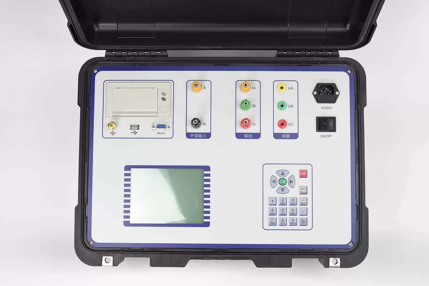
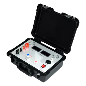
ZC-204B Transformer short-circuit impedance tester has the internal adjustable power output and do not need the outside pressure regulator, only need to provide 220V power supply can be tested, especially suitable for the field of 110kV level and above the main transformer for low voltage short circuit impedance measurement.
Kvtester Electronics Technology Co.,Ltd. is a high-tech enterprise specializing in power testing, testing, research and development, production, and sales of testing equipment. It has been engaged in the electrical testing industry for many years, and its products are of high quality. We welcome customers to come and purchase. Service hotline: 0086-27-81778799, to learn more, visit the official website: www.kvtester.com
Related Products





Latest News
-
 2026-09-21Smart Transformer Testing Equipment: Features for Efficient Testing
 -
 2026-09-21Transformer Testing Equipment for Grid Maintenance Guide
 -
 2026-09-20CT PT Analyzer for Commissioning: Substation Testing Guide
 -
 2026-09-20ANSI Standard CT Tester: Specs, Tests & Buying Guide
 -
 2026-09-18Why does the required capacity of series resonant test equipment usually increase with cable length?
