Analysis and Troubleshooting of Common Faults in High-Voltage Switch Mechanical Characteristic Testers
Analysis and Troubleshooting of Common Faults in High-Voltage Switch Mechanical Characteristic Testers
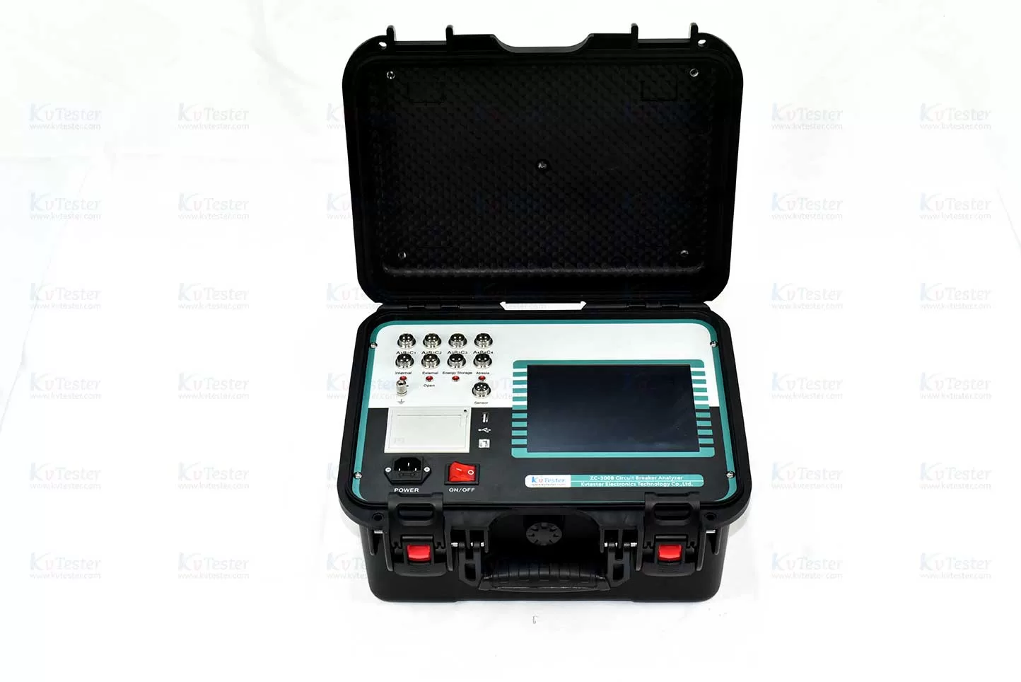
A high-voltage switch mechanical characteristic tester is an essential instrument in power systems used to evaluate the mechanical performance of high-voltage circuit breakers. It is widely utilized in substations, power maintenance facilities, and by manufacturers of high-voltage switchgear. The instrument measures parameters such as opening/closing times, synchronization, contact bounce, travel, and speed, providing critical data for assessing the mechanical condition of a circuit breaker.
During actual testing, factors such as wiring configurations, sensor installation, operating power supply, and electromagnetic interference in the field can lead to anomalous test data or equipment malfunctions. Below are several common faults and their corresponding troubleshooting methods.
1. Failure to Power On
① Symptom: The display screen remains dark after the power is turned on, or the device shuts down automatically shortly after startup.
② Potential Causes:
Poor connection of the power cord or issues with the power supply;
A blown fuse;
Insufficient charge in the internal battery or a malfunction in the power supply module.
③ Troubleshooting:
First, verify the external supply voltage and the integrity of the power cord connections to ensure they meet the instrument’s specifications. For battery-powered units, check the battery status. If the device still fails to power on, it should be inspected by a qualified technician; do not attempt to disassemble the unit, as this may cause further damage.
2. Anomalous Opening/Closing Time Data
① Symptom: Measured opening or closing times appear excessively long or short, or the device fails to detect the operation time.
② Potential Causes:
Incorrect wiring of the contact test leads or poor electrical contact;
Anomalous state of the circuit breaker’s auxiliary contacts;
Incorrect trigger mode settings on the instrument;
Malfunction in the circuit breaker’s operating mechanism.
③ Troubleshooting:
Check the wiring at the contact points and the test channel settings, ensuring that the trigger signal aligns with the circuit breaker’s operating mode. Additionally, verify the operating power supply voltage and the status of the operating mechanism. If necessary, repeat the test and compare the results.
3. Anomalous Circuit Breaker Speed and Travel Measurements
① Symptom: Measured speeds are significantly higher or lower than expected, the travel curve is discontinuous, or it is impossible to obtain valid data.
② Potential causes:
Incorrect installation position of the displacement sensor;
Sensor not securely fastened;
Incorrect sensor type or parameter settings;
Loose or damaged sensor connection cables.
③ Solutions:
Select an appropriate linear or rotary sensor based on the circuit breaker’s structure, ensuring it is securely mounted and oriented correctly relative to the direction of motion. Verify the sensor’s measurement range, transmission ratio, and instrument parameter settings, and confirm that the sensor’s operating range meets the test requirements.
4. Significant deviation in data regarding non-simultaneity of opening/closing
① Symptom: Measurement results indicate a notable increase in the non-simultaneity (asynchronicity) of the three-phase opening or closing operations.
② Potential causes:
Incorrect connection of test leads for individual phases;
Abnormal contact status at the interrupter;
Discrepancies within the circuit breaker’s mechanical transmission mechanism;
Inconsistent operation of the operating mechanisms for each phase.
③ Solutions:
First, rule out issues with wiring and test channels. Then, referring to historical test data for the circuit breaker, inspect the transmission mechanism, connecting rods, and other relevant mechanical components. For anomalous results, perform repeat tests and additional inspections to reach a comprehensive assessment.
5. No response from the instrument during testing
① Symptom: The circuit breaker fails to perform an opening or closing operation after the test is initiated.
② Potential causes:
Incorrect connection of opening/closing control cables;
Operating power supply does not meet requirements;
Circuit breaker energy-storage mechanism has not completed its charging cycle;
Control circuit is interlocked, or necessary protection/permissive conditions are not met.
③ Solutions:
Check the control wiring, operating power supply, and energy-storage status to ensure the circuit breaker is in a condition for safe operation. Troubleshooting involving control circuits must be performed by qualified personnel in accordance with on-site safety regulations; bypassing (short-circuiting) interlock circuits is strictly prohibited.
6. Significant fluctuations or poor repeatability in test data
① Symptom: Notable discrepancies in opening/closing time, speed, or travel data when the same circuit breaker is tested repeatedly.
② Potential causes:
Strong electromagnetic interference at the test site;
Inadequate shielding or grounding of test leads;
Unstable sensor installation;
Inherent fluctuations in the operation of the circuit breaker’s mechanism.
③ Solutions:
Arrange test leads reasonably, keeping them away from strong interference sources, and ensure proper grounding and shielding as specified in the instrument’s instruction manual. Check that sensors are securely mounted; then, evaluate the cause of any anomalies by considering the operating voltage, the mechanical condition of the equipment, and the results from multiple test runs.
7. How can malfunctions during high-voltage switch mechanical characteristic testing be minimized?
In daily operation, the following measures should be taken:
① Inspect the instrument, connecting cables, and sensors before testing;
② Configure test parameters correctly based on the specific circuit breaker model;
③ Follow operating procedures strictly when connecting leads and conducting tests;
④ Periodically verify the instrument’s measurement performance and ensure it is calibrated as required;
⑤ Maintain proper records of test data to facilitate historical trend analysis.
8. Conclusion
When anomalous data occurs during high-voltage switch mechanical characteristic testing, the first steps should be to check the wiring, parameter settings, sensors, and operating power supply, followed by an analysis of the circuit breaker’s mechanical condition.
Proper use of test equipment, combined with a solid grasp of troubleshooting techniques, not only enhances on-site testing efficiency but also provides a reliable technical basis for the condition-based maintenance and safe operation of high-voltage circuit breakers.
Related Products
Latest News
-
 2026-11-10Why do loop resistance testers use high-current testing? What is the difference between 100A and 200A?
-
 2026-11-10How to Choose Between 2500V and 5000V Insulation Resistance Testers? What Are the Differences?
-
 2026-11-10Working Principle and Precautions for Transformer DC Resistance Testers
-
 2026-11-10How Should Small and Medium-Sized Transformer Factories Configure Their Factory Acceptance Testing (FAT) Equipment?
-
 2026-11-05Smart CT PT Analyzer with USB Output for Easier Test Data Handling