Working Principle and Precautions for Transformer DC Resistance Testers
Working Principle and Precautions for Transformer DC Resistance Testers
1. What is a transformer DC resistance tester?
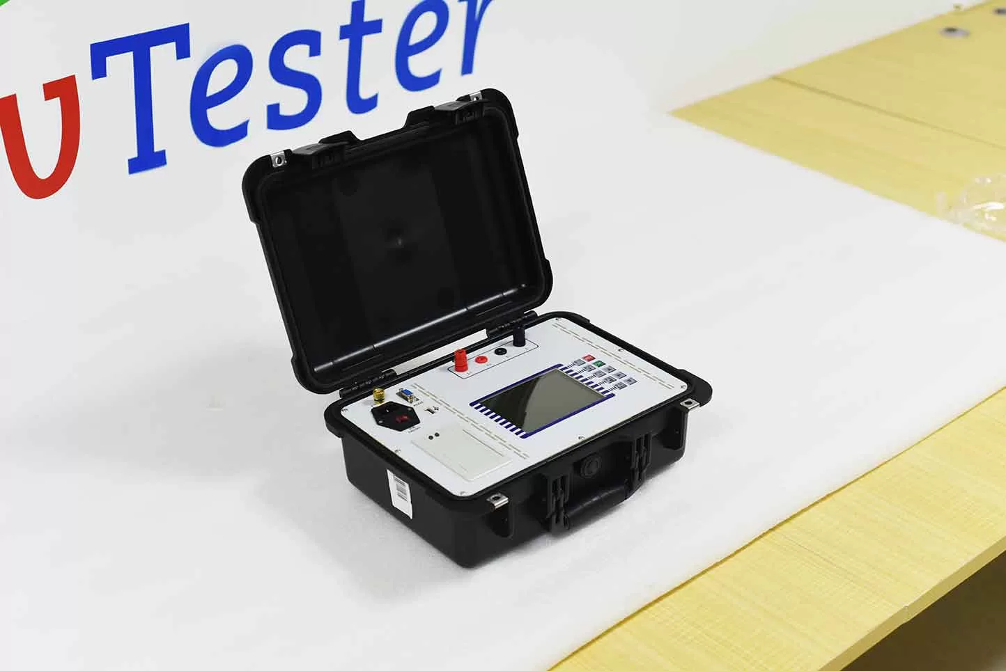
A transformer DC resistance tester is an instrument commonly used in preventive and commissioning tests for power equipment, primarily designed to measure the DC resistance of transformer windings. The test data helps identify potential anomalies in areas such as winding connections, tap-changer contact points, and lead connections. DC resistance testing is a key component of transformer condition monitoring and is widely used in power plants, substations, electrical maintenance facilities, and transformer manufacturing plants.
2. Working principle of a transformer DC resistance tester
Transformer DC resistance testers typically employ a constant-current source and a four-terminal measurement technique. By applying a stable DC current to the winding under test and measuring the voltage across it, the resistance value is calculated according to Ohm’s Law.
The fundamental formula is: R = U / I
Where:
R: DC resistance of the winding under test (in Ω);
U: Measured voltage across the winding (in V);
I: Test current flowing through the winding (in A).
The four-terminal measurement method effectively minimizes the influence of test leads and contact resistance on the measurement results, thereby enhancing accuracy.
Because transformer windings possess significant inductance, a certain amount of time is required for the current to stabilize during testing. Some intelligent DC resistance testers utilize rapid-charging and automatic current-stabilization technologies to improve efficiency during on-site testing.
3. Primary functions of transformer DC resistance testing
①. Checking the condition of winding connections
Measuring the DC resistance of windings helps detect issues such as poor-quality welds, loose connections, or abnormal contact at lead connection points.
②. Checking the condition of tap-changer contacts
By comparing DC resistance data across different tap positions, it is possible to identify potential issues, such as poor contact within the tap-changer.
③. Assessing resistance variations among three-phase windings
Under appropriate comparison conditions, analyzing the resistance data of three-phase windings can help uncover potential anomalies within the windings or their connections. ④. Assisting in the Assessment of Equipment Operating Status
By incorporating historical test data, temperature-corrected results, and other test parameters, the data can serve as a reference for assessing the condition of a transformer and making maintenance decisions.
4. Precautions for Transformer DC Resistance Testing
Before testing, ensure that the transformer is de-energized and isolated. Follow on-site safety protocols to implement necessary safety measures, such as verifying the absence of voltage and applying protective grounding.
Select an appropriate test current based on the resistance range of the winding under test and the technical specifications of the instrument.
Ensure that the test leads (clamps) are securely connected to the terminals; poor contact can adversely affect measurement results.
Record the test data only after both the test current and the resistance reading have stabilized.
Upon completion of the test, use the instrument to discharge the winding. Do not remove the test leads until the discharge process is confirmed to be complete.
When comparing measurements taken at different times, account for the effect of winding temperature and perform temperature corrections in accordance with applicable standards.
5. How to Choose the Right DC Resistance Tester?
When selecting a DC resistance tester for transformers, consider the following key factors:
① Test Current Range: Choose based on the transformer’s capacity, winding resistance, and specific testing requirements.
② Measurement Accuracy: Ensure the instrument’s accuracy meets the requirements of the intended testing task.
③ Testing Efficiency: Consider factors such as the speed at which the current stabilizes, automatic range selection, and discharge capabilities.
④ Safety Protection Features: Prioritize equipment that includes features such as discharge status indicators and protection against abnormal conditions.
⑤ On-site Usability: Select a portable or other suitable model based on specific operational needs.
6. Conclusion
A transformer DC resistance tester is an essential tool for evaluating the condition of transformer windings and their connections. Standardized testing procedures, appropriate instrument selection, and rigorous data analysis help in the early detection of potential equipment defects, providing technical support for the safe and stable operation of transformers. SEO Title
A Detailed Guide to the Operating Principle and Usage Precautions for Transformer DC Resistance Testers
Related Products
Latest News
-
 2026-11-10Analysis and Troubleshooting of Common Faults in High-Voltage Switch Mechanical Characteristic Testers
-
 2026-11-10Why do loop resistance testers use high-current testing? What is the difference between 100A and 200A?
-
 2026-11-10How to Choose Between 2500V and 5000V Insulation Resistance Testers? What Are the Differences?
-
 2026-11-10How Should Small and Medium-Sized Transformer Factories Configure Their Factory Acceptance Testing (FAT) Equipment?
-
 2026-11-05Smart CT PT Analyzer with USB Output for Easier Test Data Handling