Why do loop resistance testers use high-current testing? What is the difference between 100A and 200A?
Why do loop resistance testers use high-current testing? What is the difference between 100A and 200A?
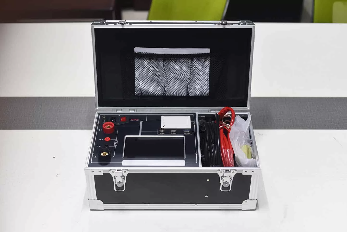
A loop resistance tester is an instrument commonly used in the maintenance and preventive testing of power equipment. It is primarily employed to measure the resistance of conductive paths in high-voltage circuit breakers, disconnect switches, and other electrical equipment. Unlike standard multimeters, loop resistance testers typically utilize a DC test current of 100A, 200A, or even higher. So, why is a high current required for loop resistance testing, and what are the advantages of doing so?
1. Operating Principle of a Loop Resistance Tester
Loop resistance testers generally employ a constant DC current source and a four-terminal measurement method. By applying a stable DC current to the conductive path under test, the instrument measures the voltage drop across the path and calculates the resistance value based on Ohm’s Law.
The calculation formula is: R = U / I
Where:
R: Resistance of the path under test (in Ω);
U: Voltage drop across the path under test (in V);
I: Test current flowing through the path under test (in A).
Since the resistance of conductive paths in high-voltage switchgear is typically in the micro-ohm (μΩ) range, high-precision measurement techniques are required to ensure the reliability of the test results.
2. Why is a high current used for loop resistance testing?
①. Improving the accuracy of measuring very low resistance
The resistance at the contacts and conductive connection points of high-voltage circuit breakers is usually extremely low. If a small test current is used, the resulting voltage drop will be very weak, making it susceptible to instrument noise, thermal electromotive force (thermal EMF), and external interference.
Using a higher test current increases the voltage drop signal across the path under test, thereby improving the signal-to-noise ratio of the measurement.
For example, assuming the resistance of the path under test is 50 μΩ:
With a test current of 1A, the voltage drop is 50 μV;
With a test current of 100A, the voltage drop is 5 mV;
With a test current of 200A, the voltage drop is 10 mV.
As this demonstrates, for a given resistance, a higher test current produces a voltage signal that is easier to measure accurately.
②. Reducing the impact of surface films on contacts
The surfaces of high-voltage switch contacts may feature oxide films or other contaminants, which can cause the contact resistance to exhibit non-linear characteristics.
Using a higher test current helps mitigate the influence of such surface films on measurement results, ensuring that test conditions more closely align with the requirements for inspecting the main circuits of high-voltage switches.
However, it should be noted that a high test current does not guarantee the complete removal of oxide films, nor can it serve as a substitute for proper contact cleaning and the inspection of contact conditions.
③. Enhancing the comparability of test results
Employing a specified test current facilitates the comparison of results for the same equipment over different periods, as well as the assessment of resistance variations between different phases.
Relevant standards for measuring the main circuit resistance of high-voltage switches typically mandate specific test currents. Therefore, using a test current that complies with these standards ensures that the inspection results meet established regulatory requirements.
3. What are the differences between 100A and 200A circuit resistance testers?
The primary difference between 100A and 200A circuit resistance testers lies in their maximum output test current.
① 100A circuit resistance tester
Suitable for measuring the conductive circuit resistance of common high-voltage circuit breakers, disconnectors, and power distribution equipment; it is a standard tool used in electrical maintenance and routine testing.
② 200A circuit resistance tester
Capable of delivering a higher test current, which can produce a stronger voltage drop signal when measuring certain low-resistance circuits. It is intended for applications that specifically require a 200A test current or where a broader range of test current options is desired.
It is important to note that a 200A rating does not necessarily imply that the measurement results will be more accurate than those obtained with a 100A tester. The accuracy of an instrument also depends on factors such as constant-current stability, the design of the measurement circuitry, immunity to interference, and the configuration of the test leads.
4. How should one choose a circuit resistance tester?
When selecting a circuit resistance tester, consider the following key factors:
① Test current: Choose a 100A, 200A, or other appropriate test current range based on the type of equipment being tested and the applicable standards.
② Measurement range: Ensure that the instrument can cover the micro-ohm (µΩ) resistance range relevant to the equipment under test.
③ Measurement accuracy: Evaluate the instrument’s accuracy, resolution, and repeatability.
④ Test Duration: Set the test duration based on the instrument’s rated operating capacity and the requirements of the equipment under test.
⑤ Ease of Operation: Prioritize instruments that feature four-terminal (Kelvin) measurement, automatic data storage, and protection against abnormal conditions.
5. What precautions should be taken during high-current testing?
Before testing, ensure that the equipment under test is de-energized and isolated. Follow on-site safety protocols to verify the absence of voltage, apply grounding, and implement other necessary safety measures.
During testing, ensure that current leads and voltage-sensing leads are connected correctly. Verify that test clamps make reliable contact, as loose connections can compromise test results.
Additionally, be aware that high currents can cause temperature rises in conductors and contact points; ensure that the test current and duration do not exceed the limits specified for either the instrument or the equipment under test.
6. Conclusion
Loop resistance testers utilize high-current testing primarily to improve signal quality when measuring micro-ohm-level resistance, minimize the influence of contact surface conditions, and comply with relevant testing standards.
For routine high-voltage switchgear inspection, a 100A loop resistance tester is highly practical; for scenarios requiring higher test currents, a 200A loop resistance tester may be selected.
Selecting appropriate test currents and instrument parameters effectively enhances the accuracy and reliability of loop resistance measurements, providing technical support for the safe operation of power equipment.
Related Products
Latest News
-
 2026-11-10Analysis and Troubleshooting of Common Faults in High-Voltage Switch Mechanical Characteristic Testers
-
 2026-11-10How to Choose Between 2500V and 5000V Insulation Resistance Testers? What Are the Differences?
-
 2026-11-10Working Principle and Precautions for Transformer DC Resistance Testers
-
 2026-11-10How Should Small and Medium-Sized Transformer Factories Configure Their Factory Acceptance Testing (FAT) Equipment?
-
 2026-11-05Smart CT PT Analyzer with USB Output for Easier Test Data Handling