
What causes a transformer’s turns ratio error to exceed the limit?
What causes a transformer’s turns ratio error to exceed the limit?
The transformer turns ratio test verifies whether the voltage ratio between the high-voltage and low-voltage windings aligns with the design specifications. An error exceeding the limit may stem from issues such as test wiring, parameter settings, the tap changer, winding turns, or internal wiring.
During troubleshooting, first verify the test conditions, then check the tap position and winding structure; avoid immediately concluding that the transformer has a manufacturing defect.
1. Incorrect test parameter input
Testing instruments typically require inputs such as rated high voltage, rated low voltage, vector group, and tap position. If nameplate parameters are entered incorrectly, the instrument calculates an incorrect standard ratio, resulting in a reported error that exceeds the limit.
Common issues include:
① Incorrect input of high- and low-voltage ratings;
② Confusion between phase voltage and line voltage;
③ Incorrect vector group selection;
④ Incorrect voltage settings for specific tap positions;
⑤ Incorrect selection of single-phase or three-phase mode.
Verify the nameplate, drawings, and instrument settings before testing.
2. Incorrect test wiring or poor contact
Incorrect phase sequence, terminal connection errors, or poor contact at the test clamps can lead to abnormal ratio data; issues such as vector group identification errors, data fluctuations, or test failure may also occur.
Check the following:
① Whether high- and low-voltage test leads are reversed;
② Whether phases A, B, and C correspond correctly;
③ Whether the neutral point connection is correct;
④ Whether test clamps are securely attached;
⑤ Whether terminal surfaces are oxidized or dirty.
After rewiring, repeat the test for each phase and compare the results.
3. Incorrect tap changer position
For transformers equipped with tap changers, different positions correspond to different winding turns and rated voltages. If the selected tap position does not match the instrument setting, a significant ratio error will occur.
Other potential issues include:
① Inconsistent tap positions across the three phases;
② Mismatch between the tap indicator and actual contact position;
③ Tap changer not fully switched to the intended position;
④ Loose or misaligned operating mechanism;
⑤ Abnormal contact at a specific tap position. If the error exceeds limits at only a specific tap position, focus the inspection on the contacts and tap leads associated with that position.
4. Incorrect winding turn count
The transformer turns ratio is primarily determined by the number of turns in the high- and low-voltage windings. Errors such as under-winding, over-winding, or miscalculation of turns during manufacturing will directly cause deviations in the turns ratio.
Such issues typically manifest as follows:
① The direction and magnitude of errors across phases are similar;
② A specific winding or tap position consistently shows high or low readings;
③ Test results remain stable upon repetition;
④ Results remain abnormal even after switching to a different tester.
In this case, it is necessary to verify the winding process records, design drawings, and actual turn counts.
5. Incorrect tap lead connections
Incorrect placement of tap leads, wrong connection sequences between taps, or misconnection of a specific tap can all lead to abnormal turns ratios at certain tap positions.
If the turns ratio at the rated tap is normal but errors are significant at one or more other taps, the following should be prioritized for troubleshooting:
① Tap positions;
② Lead numbering;
③ Tap connection sequence;
④ Wiring between the tap changer and the winding taps.
6. Internal inter-turn short circuit in the winding
An inter-turn short circuit reduces the effective number of turns, potentially altering the turns ratio.
With minor inter-turn short circuits, the change in turns ratio may not be obvious, but other symptoms often appear, such as:
① Increased no-load current;
② High no-load loss;
③ Imbalance in three-phase data;
④ Localized overheating or abnormal noise.
Therefore, if an inter-turn short circuit is suspected, a comprehensive assessment should be made by combining results from no-load tests, DC resistance tests, and insulation tests.
7. Incorrect winding connection or internal wiring
Reversed winding terminals (start/end), incorrect phase sequencing, or errors in star/delta connections can all cause abnormal turns ratio and vector group test results.
Such issues typically result in not only excessive turns ratio errors but also:
① Incorrect identification of the vector group;
② Inability to measure a specific phase;
③ Significant differences in turns ratios between phases;
④ Abnormal phase angles. Check the winding leads and internal connections against the design drawings.
8. Abnormalities in test instruments or power supply
An unstable output voltage from the turns ratio tester, a faulty measurement channel, or a lack of recent instrument calibration can cause measurement errors.
Strong electromagnetic interference, poor grounding, or the use of long test leads at the site can also lead to unstable measurement results.
Verify the instrument using a standard transformer or a unit known to be in good condition, or re-test using a different instrument.
9. Recommended troubleshooting sequence
If the turns ratio error exceeds the limit, proceed as follows:
① Verify nameplate parameters, the vector group, and instrument settings;
② Check the high- and low-voltage test leads and the three-phase phase sequence;
③ Confirm that the tap changer position matches the setting;
④ Re-test all tap positions and all three phases of the windings;
⑤ Verify the test system using another instrument or a transformer known to be in good condition;
⑥ Inspect the tap changer, tap leads, and internal wiring;
⑦ Verify the number of winding turns and conduct further analysis using DC resistance and no-load test data.
Conclusion
Common causes for excessive transformer turns ratio errors include incorrect parameter input, poor test connections, mismatched tap positions, incorrect winding turn counts, misconnected tap leads, and abnormal internal connections. During troubleshooting, first rule out issues with instrument settings and wiring, then inspect the tap changer and winding structure. If the turns ratio anomaly is accompanied by abnormal no-load loss, no-load current, or DC resistance readings, further investigation into internal winding faults is required.
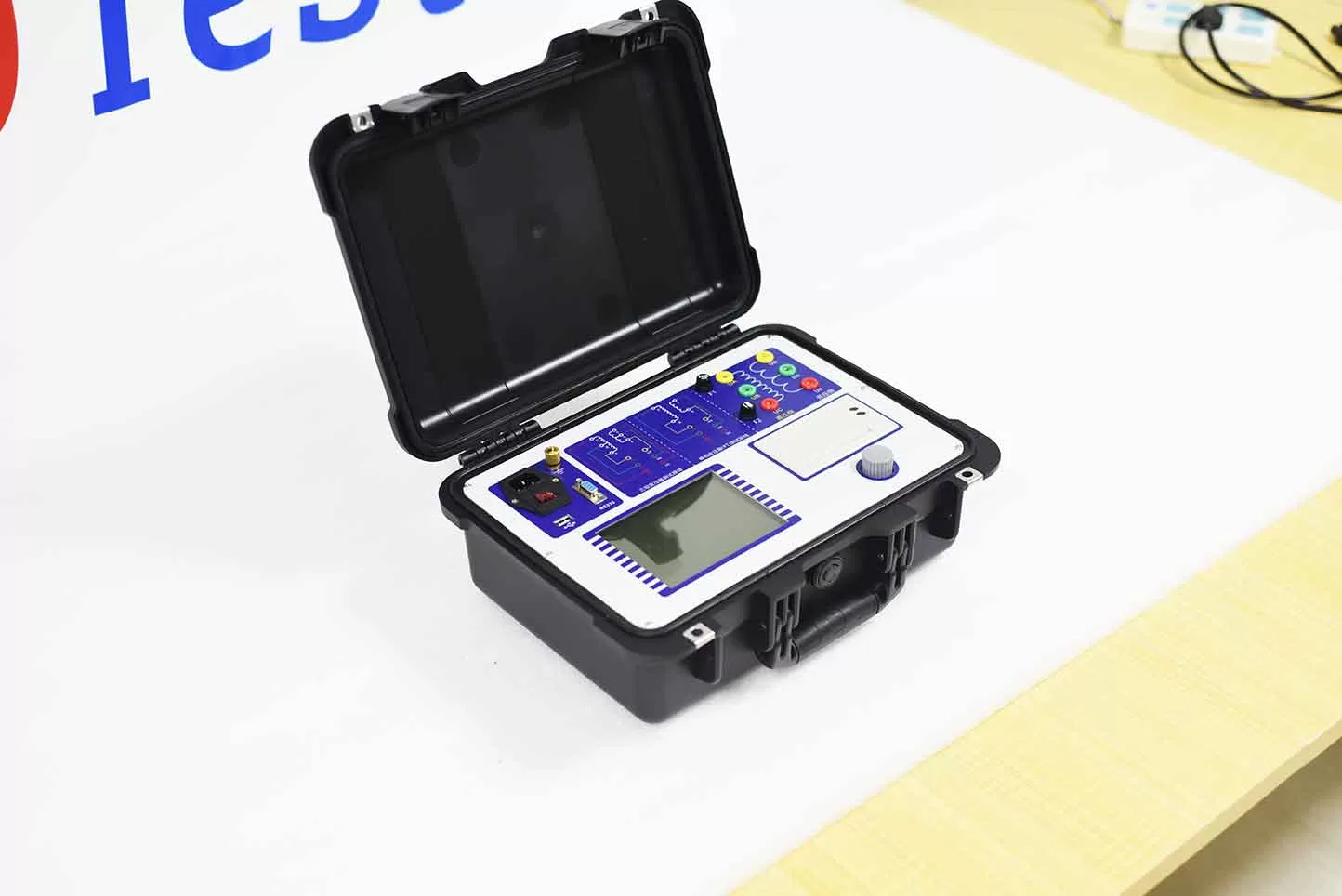
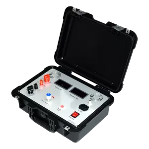
ZC-203D full function variable ratio tester is based on the original requirements of user on-site use, making the operation simpler, more complete, and the data stable and reliable, greatly improving the testing speed. The equipment is suitable for various transformer ratio tests of large, medium, and small sizes. The instrument has unique functions such as unlimited scanning codes and active data uploading. The server can centrally analyze and manage data, and export data files in Excel format, greatly improving detection efficiency and saving manpower and time. It is an ideal testing instrument for the power industry.
Kvtester Electronics Technology Co.,Ltd. is a high-tech enterprise specializing in power testing, testing, research and development, production, and sales of testing equipment. It has been engaged in the electrical testing industry for many years, and its products are of high quality. We welcome customers to come and purchase. Service hotline: 0086-27-81778799, to learn more, visit the official website: www.kvtester.com
Related Products





Latest News
-
 2026-09-21Smart Transformer Testing Equipment: Features for Efficient Testing
 -
 2026-09-21Transformer Testing Equipment for Grid Maintenance Guide
 -
 2026-09-20CT PT Analyzer for Commissioning: Substation Testing Guide
 -
 2026-09-20ANSI Standard CT Tester: Specs, Tests & Buying Guide
 -
 2026-09-18Why does the required capacity of series resonant test equipment usually increase with cable length?
