
What are the causes of excessive no-load loss in transformers?
What are the causes of excessive no-load loss in transformers?
No-load loss in a transformer primarily originates in the iron core. When rated frequency and specified voltage are applied to one winding while the other remains open-circuited, hysteresis loss and eddy current loss within the core constitute the majority of the no-load loss.
If test results significantly exceed design values or standard requirements, investigations typically focus on factors such as core materials, manufacturing processes, assembly conditions, and testing parameters.
1. Core material properties do not meet requirements
The material and properties of silicon steel sheets directly influence no-load loss. Issues such as using the wrong grade of silicon steel, high specific loss, or performance variations between material batches can all lead to increased core loss.
Additionally, moisture or rust on the silicon steel sheets—resulting from transportation, storage, or processing—can impair their magnetic properties.
2. Poor processing quality of silicon steel sheets
During shearing, stamping, and stacking, defects such as excessive burrs, dimensional deviations, or poor cut quality can compromise inter-laminar insulation and increase eddy current loss. Significant mechanical stress induced during processing can also degrade the magnetic properties of the silicon steel, resulting in higher no-load loss.
3. Improper core stacking process
Excessive gaps at core joints, misaligned laminations, incorrect joint positioning, or improper overlapping methods increase magnetic circuit reluctance, thereby raising excitation current and no-load loss. Discrepancies between the design and the actual number of laminations, stack thickness, or effective cross-sectional area can also lead to excessively high magnetic flux density.
4. Improper core clamping force
Excessive clamping force can subject silicon steel sheets to high mechanical stress, impairing magnetic properties; conversely, insufficient clamping can cause lamination vibration, joint instability, and increased noise. Therefore, clamping force must adhere to process specifications rather than simply following the principle that “tighter is better.”
5. Damaged inter-laminar insulation
Silicon steel sheets typically feature an insulating coating designed to limit eddy currents between laminations. If the insulating coating is damaged during shearing, stacking, or clamping, inter-laminar short circuits may occur, significantly increasing eddy current losses. In severe cases, localized overheating may also result.
6. Multi-point grounding of the iron core
Transformer iron cores are typically permitted to have only one reliable grounding point. If multi-point grounding occurs between the core, clamps, or metal structures, circulating currents may be generated, thereby increasing no-load losses and causing localized temperature rises.
Damage to core insulation pads, bridging by foreign objects, or abnormal contact of fasteners can all lead to multi-point grounding.
7. Deviations in core structure or dimensions
An undersized core limb cross-section, changes in magnetic path length, or window dimensions that do not meet design specifications can all alter the magnetic flux density within the core.
When magnetic flux density is excessively high, the core may approach magnetic saturation, leading to a significant increase in both no-load current and no-load losses.
8. Errors in winding turn count
Although no-load losses primarily originate from the iron core, the number of winding turns also affects the core’s magnetic flux density.
If the actual number of turns is less than the design value, the core’s magnetic flux density will rise under the same test voltage and frequency; in severe cases, over-excitation may occur, causing both no-load current and no-load losses to exceed normal limits.
9. Inaccurate test voltage or frequency
No-load losses are highly sensitive to test voltage and frequency. If the applied voltage exceeds the specified value or the test frequency is lower than the rated frequency, the core’s magnetic flux density will increase, resulting in higher measured values.
Therefore, voltage and frequency stability must be ensured during testing, and measurements must be conducted in accordance with specified test conditions.
10. Distortion of the test power supply waveform
No-load tests require the test power supply to have a high-quality sinusoidal waveform. If the power supply contains significant harmonics, causing voltage waveform distortion, the measured no-load losses may deviate from the actual values.
Under low power factor conditions, the ability of the power measuring instruments to accurately measure distorted waveforms should also be considered. 11. Issues with measuring instruments or wiring
Inadequate accuracy of voltage, current, or power measuring instruments, incorrect instrument transformer ratio settings, poor contact of test leads, and incorrect voltage sampling points can all lead to inflated no-load loss readings.
If the three-phase data shows significant imbalance, the phase sequence, wiring configuration, and instrument channel assignments should also be checked for correctness.
Conclusion
Excessive no-load loss in transformers is commonly caused by factors such as abnormal core material properties, defects in the processing or stacking of silicon steel sheets, damage to inter-laminar insulation, multi-point grounding of the core, deviations in winding turns, and inaccuracies in test voltage, frequency, or measurement systems. During troubleshooting, test conditions and instrument connections should be verified first, followed by an inspection of core materials and manufacturing processes, to avoid misidentifying testing errors as product quality issues.
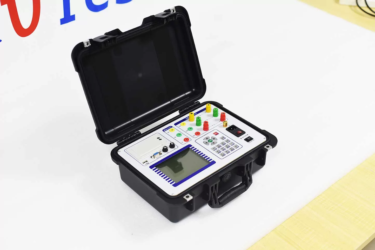
ZC-202B Transformer Capacity and Load Tester is specializing in basic electricity, power users adverse tax evasion problems and developed a new instrument to increase design.
High precision instrument for measuring characteristic parameters of transformer capacity, no-load and load. The instrument is a multi-function measuring instrument, which is equivalent to the usual two kinds of test instruments: the transformer capacity tester + transformer characteristic parameter tester. The utility model can precisely measure a series of power frequency parameters of a plurality of transformers, such as the capacity, the type, the no-load current, the no-load loss, the short circuit (load) loss and the impedance voltage.
Kvtester Electronics Technology Co.,Ltd. is a high-tech enterprise specializing in power testing, testing, research and development, production, and sales of testing equipment. It has been engaged in the electrical testing industry for many years, and its products are of high quality. We welcome customers to come and purchase. Service hotline: 0086-27-81778799, to learn more, visit the official website: www.kvtester.com
Related Products





Latest News
-
 2026-09-20CT PT Analyzer for Commissioning: Substation Testing Guide
 -
 2026-09-20ANSI Standard CT Tester: Specs, Tests & Buying Guide
 -
 2026-09-18Why does the required capacity of series resonant test equipment usually increase with cable length?
 -
 2026-09-18How should 35kV cable series resonant withstand voltage test equipment be configured?
 -
 2026-09-18How to Select AC Withstand Voltage Test Equipment for 10kV Cables?
