Home » News » Company News
CT PT Analyzer Polarity Test for Accurate CT and PT Verification
Polarity verification is an important part of current transformer (CT) and potential transformer (PT) testing. Incorrect polarity can affect the direction of current or voltage signals in metering and protection circuits, potentially leading to inaccurate measurements or abnormal relay operation. Although CTs and PTs both require polarity checks, their electrical characteristics and testing procedures are not identical.
A CT PT Analyzer can help technicians verify polarity along with other transformer parameters, such as transformation ratio, excitation characteristics, winding resistance, and burden. Understanding how CT and PT polarity tests differ is essential for selecting the correct test procedure and interpreting the results accurately.
What Is a CT PT Analyzer Polarity Test?
A CT PT Analyzer polarity test checks the relationship between the primary and secondary terminals of an instrument transformer. It helps determine whether the terminal connections follow the intended polarity markings and phase relationship.
Polarity markings identify corresponding terminals that have the same instantaneous polarity under the applicable reference convention. For example, CTs commonly use P1 and P2 for primary terminals and S1 and S2 for secondary terminals. PTs may use A, B, C and a, b, c, or other markings depending on their design.
Why Is Polarity Testing Important?
Correct polarity is necessary for instrument transformers to provide signals that correspond to the intended direction and phase relationship in the connected circuits.
For CTs, incorrect polarity can affect current direction in differential protection, directional protection, and metering circuits. It may cause measurement errors or unwanted operation of protection systems.
For PTs, incorrect polarity can affect voltage phase relationships used by meters, protection relays, and other measuring devices. This may lead to incorrect voltage measurements or unreliable protection calculations.
Polarity testing is therefore useful during transformer manufacturing, installation, commissioning, maintenance, and troubleshooting.
How to Perform a CT Polarity Test
A current transformer converts a high primary current into a smaller secondary current for measurement and protection. Its polarity test focuses on the relationship between the primary and secondary current directions.
CT Polarity Test Principle
CT polarity is commonly identified through the P1/P2 and S1/S2 terminal markings. Under the standard polarity convention, P1 and S1 are corresponding polarity terminals, as are P2 and S2.
When current enters the marked primary terminal P1, the secondary current direction follows the corresponding polarity convention. The actual current direction in the secondary circuit also depends on the connected load and the direction in which the secondary winding is traversed.
This relationship is important because protection and metering devices rely on the correct current reference direction. If the secondary connections are reversed, the measured current direction may be opposite to the intended reference.
CT Polarity Test Procedure
A CT polarity test using a CT/PT Analyzer generally involves the following steps. The exact connection method depends on the analyzer model and its supported test method.
- Check the CT nameplate: Identify the rated current ratio, terminal markings, and transformer type before testing.
- Prepare the test circuit: Isolate the CT from the relevant operating circuit according to the approved procedure. Confirm that the secondary circuit is handled safely.
- Connect the analyzer: Connect the test leads to the designated CT terminals according to the wiring diagram provided for the instrument.
- Select the CT test function: Choose the appropriate CT polarity test option and enter the required parameters if prompted.
- Start the test: Operate the analyzer and allow it to complete the measurement.
- Check the result: Compare the indicated polarity with the CT terminal markings and approved wiring diagram.
Some analyzers integrate polarity testing with other CT measurements. This can reduce repeated wiring and make it easier to review polarity alongside ratio and phase-related results.
How to Identify Incorrect CT Polarity
An abnormal polarity result indicates that the measured terminal relationship does not match the expected reference or test connection.
Before concluding that the CT itself has a polarity problem, check the following:
- Whether the P1/P2 and S1/S2 terminals have been identified correctly.
- Whether the analyzer test leads are connected to the intended terminals.
- Whether the primary conductor direction matches the test reference.
- Whether the secondary wiring corresponds to the approved drawings.
Do not reverse CT secondary connections casually, especially when the primary circuit is energized. An open CT secondary circuit can generate dangerously high voltage when primary current is flowing. Follow the approved isolation, shorting, grounding, and safety procedures before making any connection changes.
How to Perform a PT Polarity Test
A potential transformer, also called a voltage transformer, reduces high voltage to a lower standardized voltage for measurement and protection. Unlike a CT polarity test, which focuses on current direction, a PT polarity test verifies the voltage relationship between its primary and secondary windings.
PT Polarity Test Principle
PT polarity is based on the instantaneous voltage relationship between corresponding primary and secondary terminals.
Depending on the PT design, terminal markings may include A, B, C for primary connections and a, b, c for secondary connections. Single-phase units may use different combinations, such as A and N on the primary side and a and n on the secondary side.
Under the designated polarity convention, corresponding marked terminals have the same instantaneous voltage polarity. The test checks whether this relationship is consistent with the intended terminal arrangement.
For three-phase PTs, technicians must also consider phase identification and the relevant connection configuration. A correct polarity result for an individual winding does not, by itself, confirm that the complete three-phase secondary circuit has the correct phase sequence or wiring.
PT Polarity Test Procedure
The PT polarity test procedure differs from the CT procedure because the measurement is based on voltage relationships.
- Check the PT nameplate: Confirm the rated primary and secondary voltages, transformer type, and terminal markings.
- Review the connection diagram: Identify the primary and secondary terminals that should correspond.
- Prepare the PT for testing: Isolate the relevant circuits and follow the required safety procedure for the voltage level and equipment design.
- Connect the analyzer: Use the PT-specific wiring diagram supplied with the analyzer. Do not assume that CT test connections can be reused.
- Select the PT test function: Choose the appropriate PT polarity test and enter the required settings.
- Run the test: Start the measurement and wait for the analyzer to display the result.
- Verify the result: Compare the measured polarity relationship with the PT nameplate and approved wiring diagram.
The applied test signal and connection method depend on the analyzer’s design. For example, the CTA-100A uses a voltage method for CT/PT turns ratio and polarity testing. Other instruments may use different test arrangements, so the model-specific instructions must always be followed.
How to Identify Incorrect PT Polarity
An incorrect PT polarity result may indicate that the primary and secondary terminal relationship does not match the intended configuration.
Technicians should check:
- Whether the primary and secondary terminal markings have been identified correctly.
- Whether the test leads are connected to the correct PT terminals.
- Whether the selected transformer type and test settings are appropriate.
- Whether the actual wiring matches the approved connection diagram.
For three-phase PT installations, phase identification and secondary circuit connections should also be checked. If the polarity result is correct but the measured phase relationship remains abnormal, further investigation of the phase connections may be necessary.
PT testing must be performed with appropriate isolation and voltage precautions. Never apply a test signal to a PT circuit without confirming that the test arrangement is suitable for the transformer and analyzer.
CT vs PT Polarity Test: What Is the Difference?
CT and PT polarity tests share the same general purpose: verifying the relationship between primary and secondary terminals. However, they examine different electrical quantities and should not be treated as identical procedures.
The main differences are as follows:
- Test object: A CT polarity test checks a current transformer, while a PT polarity test checks a voltage transformer.
- Electrical relationship: CT polarity verification focuses on the corresponding primary and secondary current directions. PT polarity verification focuses on the instantaneous voltage relationship between windings.
- Terminal markings: CTs commonly use P1/P2 and S1/S2. PT terminal markings vary by design and may include A/B/C and a/b/c.
- Testing connections: The connection arrangements depend on the transformer type and analyzer test method. CT and PT wiring diagrams are not interchangeable.
- Application: CT polarity is particularly important for current-based metering and protection circuits. PT polarity is important for voltage measurement, phase-related calculations, and voltage-based protection.
One important point is that polarity testing should not be confused with phase sequence testing. Polarity checks the relationship between corresponding winding terminals, whereas phase sequence testing determines the order of phases in a three-phase system. Both may be necessary when verifying a complete instrument transformer installation.
How Does a CT PT Analyzer Simplify Polarity Testing?
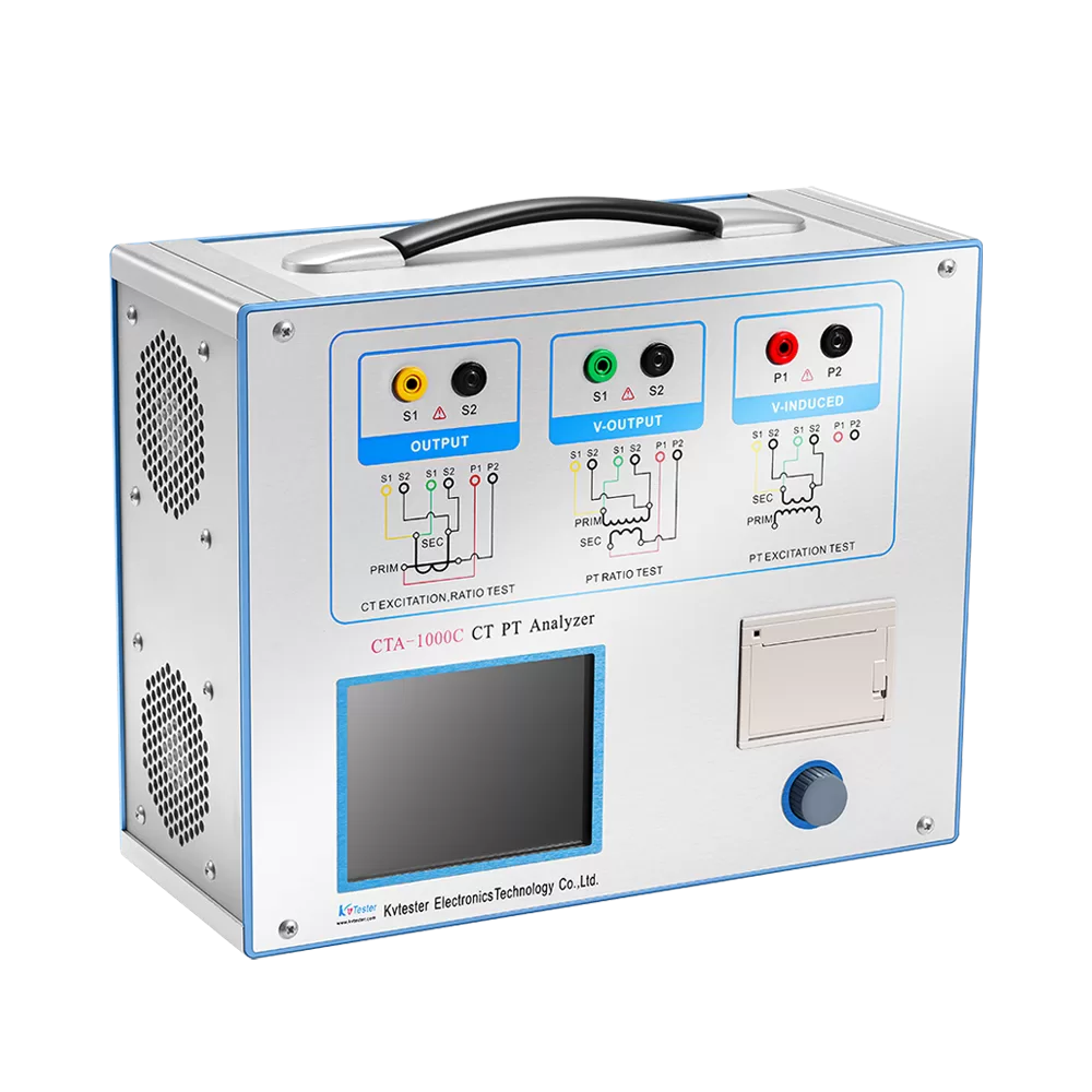
A dedicated CT/PT Analyzer can combine polarity verification with several other instrument transformer tests. Instead of relying on separate instruments for every measurement, technicians can use one testing platform for a broader evaluation of CT and PT performance.
Integrated CT and PT Testing Functions
The available functions depend on the analyzer model. Common testing capabilities include:
- CT and PT transformation ratio measurement.
- CT and PT polarity verification.
- CT excitation characteristic testing.
- PT excitation characteristic testing for supported electromagnetic units.
- Secondary winding resistance measurement.
- Secondary burden measurement.
- Ratio error and phase angle error analysis where supported.
For example, our CTA-1000D CT/PT Analyzer supports CT polarity and PT polarity testing, along with other measurements such as excitation characteristics, burden impedance, and winding resistance. It can help technicians evaluate multiple transformer parameters during routine testing and maintenance.
For another testing approach, our CTA-100A CT/PT Analyzer uses a low-frequency method for CT/PT excitation characteristic testing and a voltage method for CT/PT turns ratio and polarity testing. Its ratio measurement range is 1–40,000 for both CTs and PTs.
These examples also show why it is important to check the technical specifications of each model rather than assume that every CT/PT Analyzer uses the same test principle or supports identical functions.
Automatic Testing and Result Evaluation
Automatic testing functions can simplify the measurement process by guiding technicians through parameter settings, test selection, and result display.
Depending on the instrument, a CT/PT Analyzer may provide automatic parameter calculation, test result storage, and report analysis software. These functions help technicians organize test records and compare results during maintenance or factory inspection.
However, an automatic polarity result should not replace a physical wiring check. Technicians still need to compare the test results with the transformer nameplate, terminal markings, and approved circuit drawings.
Common Problems During CT and PT Polarity Testing
Even when using an automatic analyzer, incorrect connections or settings can affect the test results. The following issues are worth checking when the measured polarity does not match expectations.
Incorrect test lead connections
Connecting the test leads to the wrong terminals can produce an unexpected polarity result. Review the instrument’s wiring diagram and verify every connection before starting the test.
Wrong terminal identification
CT and PT terminal markings vary depending on transformer design. Do not rely on assumptions based only on terminal position or appearance. Check the nameplate and wiring documentation.
Incorrect transformer settings
The selected transformer type, rated ratio, or test parameters may not match the unit being tested. Confirm the settings before repeating the measurement.
Unexpected polarity results
An abnormal result may come from incorrect test connections, reversed secondary wiring, or an issue with the transformer itself. Check the external wiring first and then perform additional tests if necessary.
Differences between field wiring and drawings
A transformer may pass an individual polarity test while its installed secondary circuit still differs from the approved design. Compare the actual terminal connections with the complete wiring diagram before returning the equipment to service.For more information about the wider testing process, see our guide on how to test CT and PT.
Conclusion
CT and PT polarity tests are both essential for verifying instrument transformer connections, but they focus on different electrical relationships. CT polarity testing checks the relationship between primary and secondary current directions, while PT polarity testing verifies the corresponding voltage polarity between windings.
Using a suitable CT/PT Analyzer can make these tests more convenient and help technicians evaluate other transformer parameters in the same workflow. The key is to select the correct test function, follow the model-specific wiring instructions, and verify the results against the transformer markings and approved drawings.
If you are looking for a CT/PT testing solution for manufacturing, commissioning, or maintenance applications, contact Kvtester to discuss your testing requirements and find a suitable analyzer.
Related Products
Latest News
-
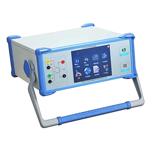 2026-11-11Digital CT PT Analyzer for Smarter Transformer Testing
-
 2026-11-11Resonant Test System Commissioning for Reliable High-Voltage Testing
-
 2026-11-11Intelligent Transformer Testing Equipment Supplier
-
 2026-11-10Analysis and Troubleshooting of Common Faults in High-Voltage Switch Mechanical Characteristic Testers
-
 2026-11-10Why do loop resistance testers use high-current testing? What is the difference between 100A and 200A?