Home » News » Company News
Resonant Test System Commissioning for Reliable High-Voltage Testing
How can a variable frequency resonant test system be properly commissioned before high-voltage testing? What should engineers check during installation, how can they find the resonant frequency, and which functions need to be verified before operation? Proper resonant test system commissioning helps ensure that equipment is correctly installed, configured, and ready for its intended test applications. Understanding each commissioning stage also helps reduce setup errors and identify potential problems before formal testing begins.
What Is Resonant Test System Commissioning?
Resonant test system commissioning refers to the inspection, installation, configuration, and functional verification of a series resonant test system before it is put into service.
The purpose is to confirm that all system components work together correctly and that the equipment can operate within its specified technical parameters.
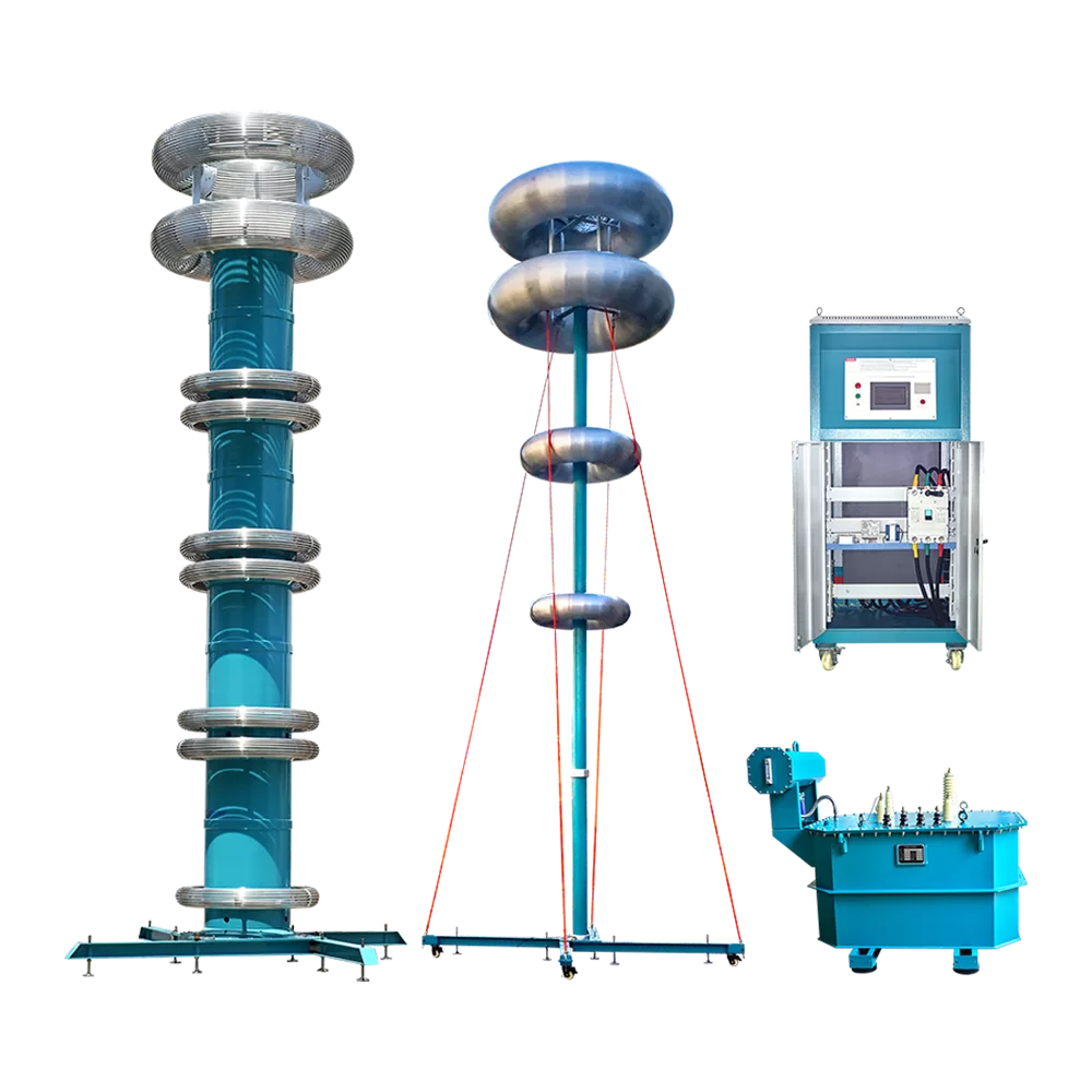
A typical variable frequency series resonant test system consists of four main components:
- Variable Frequency Power Supply: Converts the input power into an adjustable-frequency output.
- Excitation Transformer: Raises the output voltage of the frequency converter to the required excitation level.
- High-Voltage Reactor: Forms a resonant circuit with the capacitance of the test object.
- Capacitive Voltage Divider: Measures the test voltage and provides feedback for voltage monitoring and protection.
These components work together to generate the required high voltage through series resonance. Commissioning verifies their connections, control functions, and operating conditions before actual testing.
What Should Be Prepared Before Commissioning a Resonant Test System?
Adequate preparation helps prevent unnecessary interruptions during commissioning. Before starting, engineers should check the installation environment, electrical connections, test object, and safety arrangements.
Check the Installation Environment
The installation area should provide sufficient space for positioning the reactor, excitation transformer, frequency conversion power supply, and voltage divider.
Consider the following conditions:
- A stable and suitable installation surface.
- Adequate clearance between high-voltage components and surrounding objects.
- Suitable ventilation and environmental conditions.
- A clearly defined high-voltage test area.
- Proper grounding arrangements.
The actual installation requirements should follow the equipment drawings and technical documentation.
Confirm the Power Supply and Grounding
Check whether the available power supply matches the rated input requirements of the frequency conversion power supply.
For example, the Kvtester ZCVF-A series supports different input configurations depending on the model. The ZCVF-A-1000kVA/400kV system supports three-phase 380V or single-phase 220V input.
Grounding connections should also be inspected before energizing the equipment. All grounding points must follow the system wiring diagram and applicable safety requirements.
Check the Test Object Parameters
The capacitance of the test object directly affects the resonant frequency and the configuration required for testing.
Before commissioning, confirm:
- Rated voltage of the test object.
- Test voltage and required withstand time.
- Test object capacitance.
- Expected operating frequency.
- Required system capacity.
These parameters help determine whether the selected reactor combination can meet the testing requirements.
How to Install and Connect a Resonant Test System
Correct installation and electrical connections are essential for reliable system operation.
Position the Main Components
Place the variable frequency power supply, excitation transformer, high-voltage reactor, and capacitive voltage divider according to the system layout.
For systems with multiple reactors, the reactor combination should match the required test voltage and capacitance range.
For example, our ZCVF-A-1000kVA/400kV Variable Frequency Series Resonant Test System uses a modular reactor design. It is configured for AC withstand voltage testing of 10kV to 220kV cables, as well as selected GIS, switchgear, and transformer applications.

Check the Electrical Connections
After positioning the components, inspect the connections between the main units.
Pay particular attention to:
- Power connections between the frequency converter and excitation transformer.
- High-voltage connections between the excitation transformer and reactor assembly.
- Connections between the reactor and test object.
- Voltage divider measurement connections.
- Protective grounding connections.
Compare the completed wiring with the manufacturer’s drawings. Incorrect connections can affect tuning, voltage measurement, and protection functions.
How to Commission a Resonant Test System Step by Step
Once installation and connection checks are complete, commissioning can proceed through several controlled stages. The exact procedure depends on the equipment model and its operating instructions.
Step 1: Inspect the Equipment Before Power-On
Check the equipment appearance, cable connections, grounding, and control components.
Confirm that all required components are installed and that no visible damage or loose connections are present.
Step 2: Start the Control System
Power on the control system according to the manufacturer’s instructions.
Check whether the display, control interface, parameter settings, and communication functions operate normally.
For intelligent resonant test systems, the control interface should provide access to important operating information, including output voltage, frequency, current, and protection status.
Step 3: Set the Test Parameters
Enter the required test parameters according to the test object and approved test plan.
These may include:
- Target test voltage.
- Starting and ending frequency.
- Voltage boosting settings.
- Withstand voltage duration.
- Overvoltage and overcurrent protection values.
The settings must remain within the equipment’s rated operating range.
Step 4: Find the Resonant Frequency
Frequency tuning is one of the most important stages of resonant system commissioning.
The system adjusts its output frequency to match the resonance condition between the reactor inductance and the capacitance of the test object.
The resonant frequency is determined by:
[
f=\frac{1}{2\pi\sqrt{LC}}
]
Where:
- (f) = Resonant frequency (Hz)
- (L) = Total circuit inductance (H)
- (C) = Test object capacitance (F)
Many variable frequency resonant systems support automatic frequency scanning. Operators can use the frequency scanning curve to identify the resonance point and check whether the selected reactor configuration is suitable.
Step 5: Verify Voltage Control and Protection
After tuning, verify the voltage control and protection functions according to the commissioning procedure.
Check the response of overvoltage, overcurrent, detuning, zero-position, and flashover protection where these functions are provided.
Voltage boosting and high-voltage verification must be performed by qualified personnel under the manufacturer’s approved operating procedure. Do not bypass protective functions to force the system into operation.
Common Problems During Resonant Test System Commissioning
Some problems may appear during initial setup or frequency tuning. Identifying their possible causes helps engineers carry out more systematic checks.
| Problem | Possible areas to check |
| Unable to find the resonant point | Test object capacitance, reactor combination, and frequency range |
| Output voltage cannot reach the target | Power supply, system configuration, load conditions, and protection status |
| Overcurrent protection activates | Circuit connections, load conditions, and parameter settings |
| Resonant frequency is unstable | Test object connections, system configuration, and frequency control |
| Unexpected protection activation | Protection settings, grounding, wiring, and abnormal operating conditions |
Protection activation should not automatically be treated as an equipment fault. It may indicate that the system has detected an abnormal condition.
Engineers should identify the cause before restarting the test. If the problem cannot be resolved through the prescribed checks, contact the equipment manufacturer for technical assistance.
How to Verify System Performance After Commissioning
Completing installation and tuning does not necessarily mean that commissioning is finished. The system should also undergo functional verification to confirm that it meets the required operating conditions.
Check Output Voltage and Frequency
Verify that the output voltage and frequency can reach the specified values for the intended application.
For example, the Kvtester ZCVF-6000kVA/1000kV variable frequency resonant test system has the following main specifications:
- Rated capacity: 6,000 kVA.
- Rated voltage: 1,000 kV.
- Rated current: 6 A.
- Working frequency: 30–300 Hz.
- Voltage stability: Up to 1.0%.
Its frequency range can also be configured in different sections, including 30–300 Hz, 45–100 Hz, and 200–300 Hz.
These parameters provide reference points for checking whether the system configuration matches the intended test requirements.
Verify Control and Protection Functions
Check the system’s automatic, semi-automatic, and manual operating modes where available.
Protection functions should also be verified according to the manufacturer’s prescribed test methods. These may include overvoltage, overcurrent, detuning, zero-position, and flashover protection.
Review Test Data and Records
A complete commissioning process should include the recording of relevant test results and equipment settings.
Our ZCVF-6000kVA/1000kV Variable Frequency Resonant Test System supports test data storage, review, printing, and USB data output. It can store up to 50 test records, helping operators maintain commissioning and testing information.

How Professional Commissioning Support Improves System Operation
The commissioning process involves more than checking individual components. Engineers also need to understand system configuration, tuning procedures, control functions, and site-specific installation conditions.
At Kvtester, we provide technical support for the installation, debugging, testing, and operation of high-voltage resonant test systems.
For example, during a project involving a 6,000kVA/1000kV resonant test system, our engineering team traveled to the customer’s facility to complete equipment positioning, wiring, and preliminary debugging. We also provided on-site training covering equipment operation, maintenance, and fault troubleshooting.
This project demonstrates the importance of coordinating equipment installation, commissioning, and operator training. More details are available in our variable frequency series resonance test system commissioning case.
For customers who need a better understanding of system components and operating principles, our variable frequency series resonance testing system guide also explains the main components, resonance principle, and typical applications.
Conclusion
Successful resonant test system commissioning requires careful preparation, correct component installation, reliable electrical connections, accurate parameter settings, and systematic performance verification. Frequency tuning and protection checks are particularly important because they directly affect the system’s ability to perform high-voltage tests safely and reliably.
At Kvtester, we provide variable frequency series resonant test systems and technical support for different high-voltage testing applications. Contact our team to discuss your project requirements and find a suitable system configuration and commissioning solution.
Related Products
Latest News
-
 2026-11-11Digital CT PT Analyzer for Smarter Transformer Testing
-
 2026-11-11CT PT Analyzer Polarity Test for Accurate CT and PT Verification
-
 2026-11-11Intelligent Transformer Testing Equipment Supplier
-
 2026-11-10Analysis and Troubleshooting of Common Faults in High-Voltage Switch Mechanical Characteristic Testers
-
 2026-11-10Why do loop resistance testers use high-current testing? What is the difference between 100A and 200A?