How to Test CT and PT?
I. Overview
Current Transformers (CTs) and Potential Transformers (PTs) are critical measurement and protection components within power systems. Their primary function is to transform high-magnitude currents and voltages into standardized current or voltage signals that are compatible with instrumentation or protective relaying devices. To ensure measurement accuracy and system safety, CTs and PTs must undergo periodic inspection and calibration.
II. Testing Methods for Current Transformers (CTs)
1. DC Resistance Test
① Purpose: To verify the integrity of the windings and the quality of electrical contacts.
② Method:
Use a precision DC resistance tester to measure the resistance of both the primary and secondary windings.
Compare the measured values against the nominal values specified on the nameplate.
③ Precautions: During testing, the CT must be disconnected from the power system to prevent equipment damage caused by accidental operation.
2. Turns Ratio Test
① Purpose: To confirm the accuracy of the CT’s turns ratio.
② Method:
Inject a standard current into the primary winding.
Measure the resulting output current from the secondary winding.
Calculate the actual turns ratio and compare it with the rated turns ratio.
③ Tools: A CT turns ratio tester, an AC power source, or a standard current source.
3. Polarity Check
① Purpose: To ensure that the CT’s wiring polarity is correct, thereby preventing erroneous operation of protective relaying systems.
② Method:
Inject a small DC current into the primary winding.
Measure the direction of the current flowing in the secondary winding.
Verify that the marked polarity corresponds correctly to the measured direction.
4. Insulation Test
① Purpose: To assess the insulation condition between the CT windings and the core, as well as between the windings themselves.
② Method:
Use a megohmmeter (insulation resistance tester) to measure the insulation resistance of both the primary and secondary windings.
Record the insulation resistance values and ensure they meet the required standards (typically > 1 MΩ).
③ Precautions: When performing high-voltage insulation tests, ensure that the secondary winding is short-circuited to prevent the generation of high-voltage surges.
III. Testing Methods for Potential Transformers (PTs)
1. Insulation Resistance Test
Similar to the CT insulation test, with a specific focus on checking the insulation between the primary winding and the secondary winding/core.
2. Turns Ratio and Polarity Test
① Method:
Apply a standard voltage to the primary winding.
Measure the resulting output voltage from the secondary winding. Calculate the transformation ratio and verify it against the nominal value.
Check the polarity to ensure that the wiring is correct.
3. Load Test
① Objective: To verify the accuracy of the PT under rated load conditions.
② Method:
Simulate actual operating conditions using resistive or capacitive loads.
Measure the output voltage to evaluate the PT’s performance.
③ Precautions: This test must be conducted within safe limits to avoid overloading the device.
IV. Commonly Used Testing Equipment
1. CT/PT Ratio Tester: Used for testing transformation ratio, polarity, and linearity errors.
2. Megohmmeter: Used for measuring insulation resistance.
3. DC Resistance Tester: Used for measuring winding resistance.
4. AC Power Supply / Standard Current Source: Used to apply standard test signals.
V. Important Considerations
Before testing, disconnect the power supply to the relevant circuits to ensure safety.
During the testing process, pay close attention to polarity and wiring to avoid damaging the instruments.
For CTs or PTs exhibiting abnormal test results, further inspection of the windings and insulation—or replacement of the equipment—is required.
Regular testing helps extend the service life of the equipment and ensures the accuracy of relay protection and measurement systems.
The testing of CTs and PTs is a critical component in safeguarding the safety and precise operation of power systems. By employing methods such as DC resistance, insulation resistance, transformation ratio, polarity, and load testing, one can comprehensively assess the condition of CTs and PTs, thereby providing a reliable guarantee for the operation of the power system.
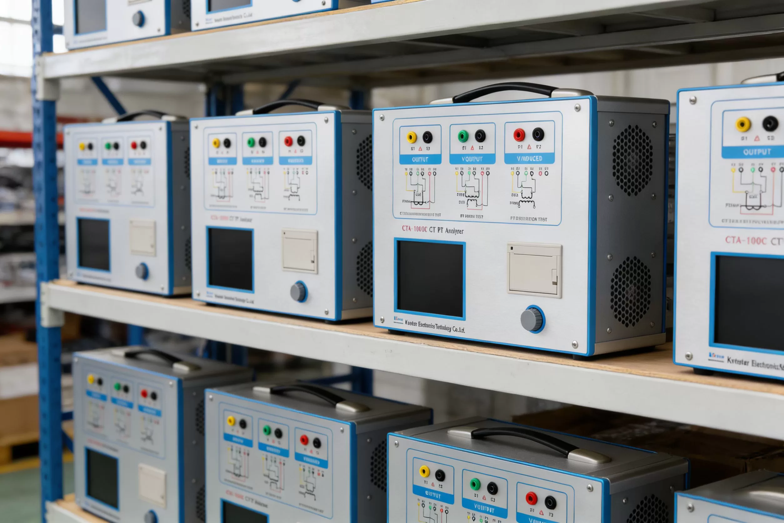
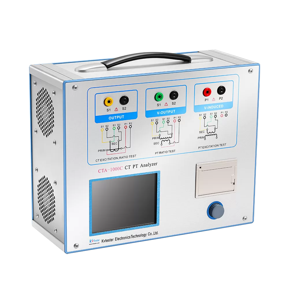
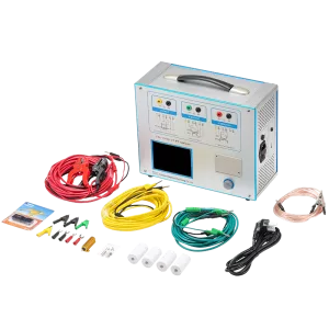
CTA-1000C Series CT Analyzer automatically determines all relevant current transformer values and compares the results with the selected standard, include excitation data, saturation inflection point, remanence coefficient, accuracy limit overcurrent factor, ratio and error data. The device evaluates the current transformer as per the IEC or IEEE standard within seconds with the push of a button.It facilitates fast and economical on-site testing and calibration of metering and protection current transformers. Manufacturers of current transformers, high voltage transformers and switchgear also use the CT Analyzer for tests during development and production.
Kvtester Electronics Technology Co.,Ltd. is a high-tech enterprise specializing in power testing, testing, research and development, production, and sales of testing equipment. It has been engaged in the electrical testing industry for many years, and its products are of high quality. We welcome customers to come and purchase. Service hotline: 0086-27-81778799, to learn more, visit the official website: www.kvtester.com
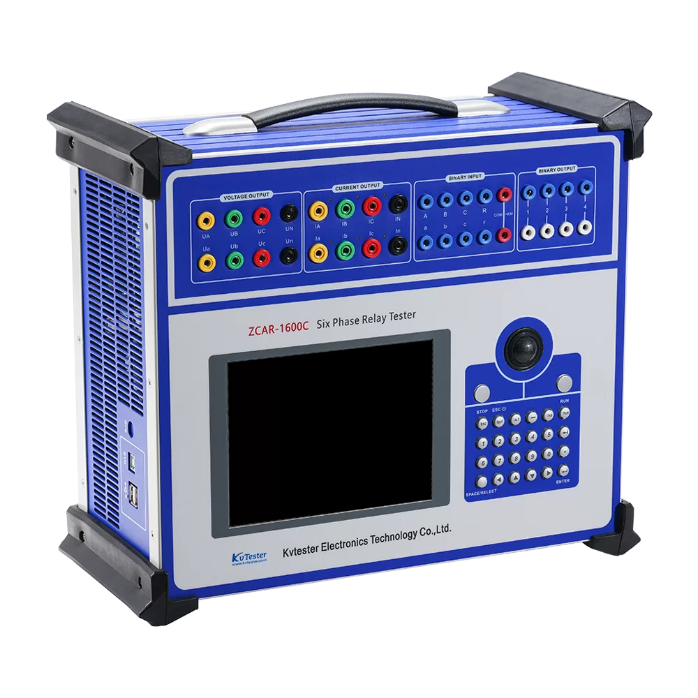
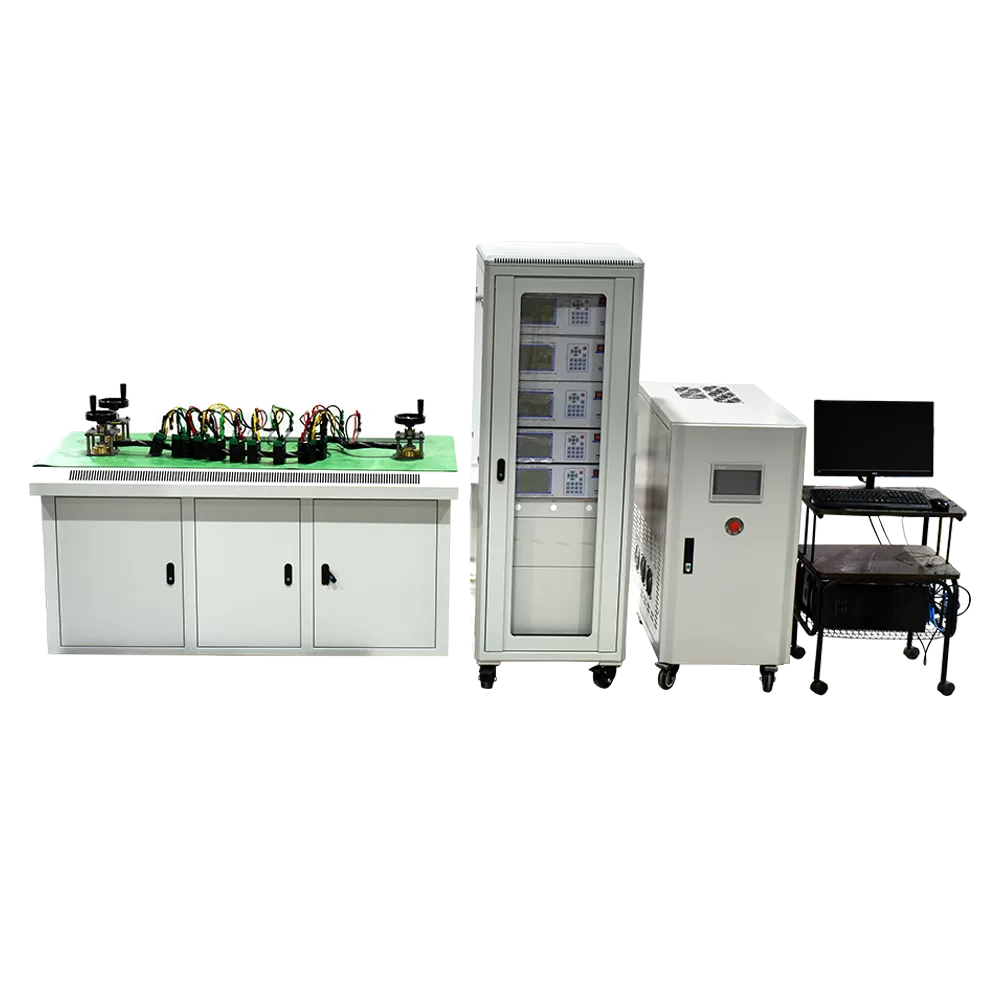
Related Products
Lasted News
-
 2026-07-24How to Select a Transformer Comprehensive Test Bench?
 -
 2026-07-24Comprehensive Overview of Transformer Factory Acceptance Tests
 -
 2026-07-24How to Choose Multi-function CT Tester | CTA-1000D vs OMICRON
 -
 2026-07-24What Are CT Testers & Working Principle in Transformer Factory
 -
 2026-07-24How to Test Current Transformers with a CT Analyzer