
What is the difference between no-load loss and load loss?
What is the difference between no-load loss and load loss?
Both no-load loss and load loss are important indicators for evaluating transformer performance, but they differ in their causes, testing methods, and influencing factors. Simply put, no-load loss primarily originates from the iron core, while load loss primarily originates from the windings.
1. What is no-load loss?
No-load loss refers to the active power consumed when rated frequency and specified voltage are applied to one side of the transformer while the other side remains open-circuited. In this state, the transformer carries no actual load, but magnetic flux is established within the iron core, resulting in power loss.
No-load loss primarily includes:
① Iron core hysteresis loss;
② Iron core eddy current loss;
③ Minor additional losses.
It is mainly related to the core material, silicon steel sheet thickness, lamination process, core structure, operating voltage, and frequency. Excessive no-load loss may be attributed to poor core material properties, improper core assembly, damaged insulation between silicon steel sheets, multi-point grounding of the core, or abnormal test voltage waveforms.
2. What is load loss?
Load loss refers to the loss caused by winding resistance and leakage magnetic fields when the transformer operates at a specified current.
Load loss primarily includes:
① Copper or aluminum losses caused by winding resistance;
② Losses in leads and connection points;
③ Additional losses caused by leakage magnetic fields;
④ Eddy current losses in structural components.
Load loss is closely related to winding materials, conductor cross-sectional area, winding structure, connection quality, test current, and temperature. Excessive load loss may be attributed to insufficient conductor cross-sectional area, high winding resistance, poor welding or connections, unreasonable winding structure, or excessive additional losses.
3. Key Differences Between the Two
| Comparison Item | No-Load Loss | Load Loss |
| Primary Source | Core | Windings, leads, and structural components |
| Main Influencing Factors | Voltage, frequency, core material, and manufacturing process | Current, temperature, conductor material, and winding structure |
| Test Conditions | Voltage applied to one side; other side open-circuited | One side short-circuited; rated current applied to the other side |
| Relationship with Load | Minimal variation when operating voltage is stable | Increases as load current increases |
| Primary Issues Revealed | Core performance and assembly quality | Winding losses and connection quality |
4. Why Perform Both Tests?
No-load loss and load loss reflect the performance of different parts of the transformer.
Measuring only no-load loss makes it impossible to determine if the windings and connections are sound; conversely, measuring only load loss cannot evaluate the core material or core assembly quality. Therefore, factory acceptance tests for transformers typically require both no-load and load tests.
By analyzing data from both tests, one can comprehensively assess:
① The stability of the transformer manufacturing process;
② The soundness of the core and winding design;
③ Whether product energy efficiency meets requirements;
④ Whether actual operational energy losses fall within a reasonable range.
5. What Should Be Noted During Testing?
For no-load loss testing, focus on test voltage, frequency, and waveform quality. Voltage deviations or waveform distortions can affect test results.
For load loss testing, accurately measure the test current and winding temperature. Since winding resistance varies with temperature, the measured load loss usually requires conversion to a specified reference temperature before evaluation.
Conclusion
No-load loss primarily reflects losses generated by the transformer core, while load loss primarily reflects losses generated by windings and related components under current flow. The former focuses on core material and manufacturing processes, whereas the latter focuses on winding resistance, connection quality, and structural design. Only by combining these two tests can one comprehensively evaluate the transformer’s energy efficiency and manufacturing quality.
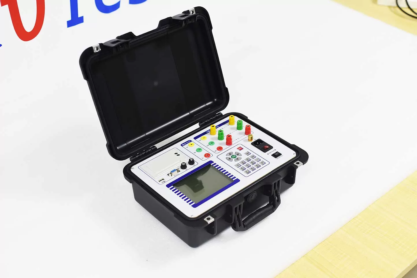
ZC-202B Transformer Capacity and Load Tester is specializing in basic electricity, power users adverse tax evasion problems and developed a new instrument to increase design.
High precision instrument for measuring characteristic parameters of transformer capacity, no-load and load. The instrument is a multi-function measuring instrument, which is equivalent to the usual two kinds of test instruments: the transformer capacity tester + transformer characteristic parameter tester. The utility model can precisely measure a series of power frequency parameters of a plurality of transformers, such as the capacity, the type, the no-load current, the no-load loss, the short circuit (load) loss and the impedance voltage.
Kvtester Electronics Technology Co.,Ltd. is a high-tech enterprise specializing in power testing, testing, research and development, production, and sales of testing equipment. It has been engaged in the electrical testing industry for many years, and its products are of high quality. We welcome customers to come and purchase. Service hotline: 0086-27-81778799, to learn more, visit the official website: www.kvtester.com
Related Products





Latest News
-
 2026-09-20CT PT Analyzer for Commissioning: Substation Testing Guide
 -
 2026-09-20ANSI Standard CT Tester: Specs, Tests & Buying Guide
 -
 2026-09-18Why does the required capacity of series resonant test equipment usually increase with cable length?
 -
 2026-09-18How should 35kV cable series resonant withstand voltage test equipment be configured?
 -
 2026-09-18How to Select AC Withstand Voltage Test Equipment for 10kV Cables?
