
How should testing equipment for 10 kV transformers be configured?
How should testing equipment for 10 kV transformers be configured?
The configuration of testing equipment for 10 kV transformers cannot be determined solely by the voltage rating; it must be decided based on a comprehensive assessment of transformer capacity, product type, specific test items, testing volume, and on-site power supply conditions.
Generally, a testing system for 10 kV distribution transformers should cover standard routine factory tests, such as DC resistance, turns ratio, no-load loss, load loss, insulation resistance, and withstand voltage tests.
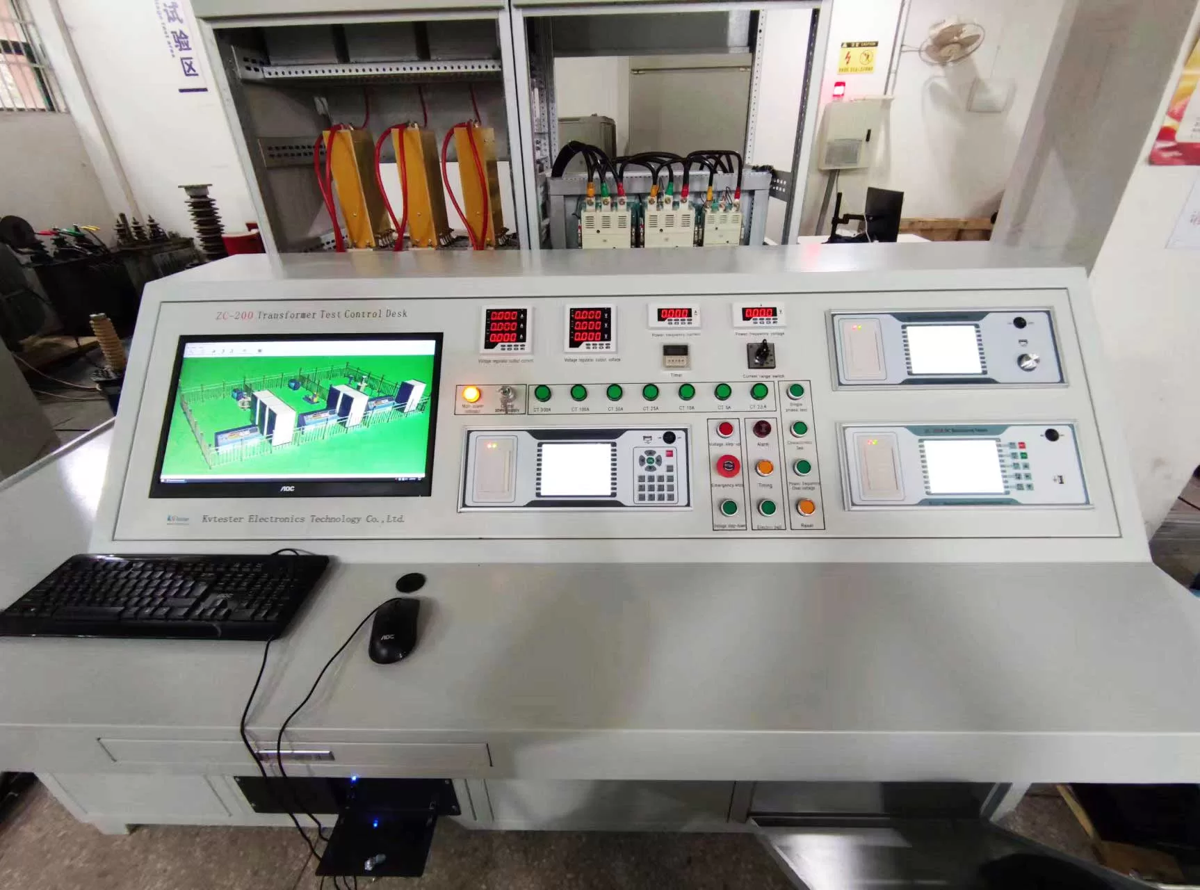
1. Integrated Control Console
The integrated control console serves as the core of the entire testing system, handling power supply control, instrument switching, safety protection, and data management. It should typically feature:
① Voltage regulation control;
② Voltage, current, and power data acquisition;
③ Test circuit switching;
④ Over-voltage, over-current, and short-circuit protection;
⑤ Zero-position start and emergency stop functions;
⑥ Audible/visual alarms and safety interlocks;
⑦ Data storage and report generation.
For enterprises with high testing volumes, a fully automated control system can be configured to minimize manual wiring, recording, and calculations.
2. DC Resistance Tester
Used to measure the DC resistance of each phase in both high- and low-voltage windings and to determine the balance of the three-phase resistance.
The equipment’s measurement range and test current should accommodate the largest capacity transformers produced by the enterprise. For low-voltage, high-current windings, particular attention should be paid to the stability and accuracy of low-resistance measurements.
3. Turns Ratio and Vector Group Tester
Used to measure the transformer’s turns ratio, ratio error, polarity, and connection group.
For 10 kV transformers with multiple tap positions, the instrument should support step-by-step testing for each tap and automatically identify common connection groups.
4. No-Load and Load Loss Testing System
No-load and load tests typically require the following configuration:
① Voltage regulator;
② Intermediate transformer or current boosting device;
③ Voltage transformer;
④ Current transformer;
⑤ Power analyzer;
⑥ Compensation device;
⑦ Automated data acquisition software.
No-load testing focuses on power measurement accuracy under low power factor conditions, while load testing focuses on rated current, short-circuit impedance, and sustained current-boosting capability. 5. Insulation resistance testing equipment
Used to measure insulation resistance between high-voltage windings, low-voltage windings, and windings to ground.
The test voltage settings must align with the insulation test requirements for 10 kV transformers. Upon completion of the test, the equipment must feature reliable automatic or manual discharge mechanisms.
6. Power-frequency withstand voltage testing equipment
A power-frequency withstand voltage system typically includes:
① Power-frequency test transformer;
② Voltage regulator;
③ High-voltage measurement device;
④ Current-limiting protection device;
⑤ Control unit;
⑥ Discharge device;
⑦ Safety fencing and high-voltage interlocks.
The output voltage and capacity of the test transformer must be selected based on the withstand voltage rating and capacitance of the transformer under test; they cannot be determined simply based on the “10 kV” rating.
7. Induced withstand voltage testing equipment
If an induced withstand voltage test is required, a variable-frequency or frequency-multiplying power supply must also be configured. This equipment is primarily used to check insulation between turns, layers, and sections of the windings. Configuration specifications should confirm:
① Maximum output voltage;
② Output frequency range;
③ Rated capacity;
④ Continuous operation duration;
⑤ Whether simultaneous partial discharge measurement is required.
For some small and medium-sized 10 kV distribution transformers, the inclusion of this test item may be determined based on product standards and technical agreements.
8. Insulating oil and accessory testing equipment
For oil-immersed 10 kV transformers, the following may also be configured:
① Insulating oil dielectric strength tester;
② Oil sample analysis equipment;
③ Sealing test apparatus;
④ Testing tools for thermometers, oil level gauges, and pressure relief devices;
⑤ Tap changer testing apparatus.
For dry-type transformers, the focus should be on configuring testing equipment for temperature controllers, cooling fans, and over-temperature alarm functions.
9. Testing software and reporting system
An automated testing system should typically feature:
① Product parameter entry;
② Test protocol selection;
③ Automatic data acquisition;
④ Automatic calculation of losses and impedance;
⑤ Automatic temperature correction;
⑥ Pass/fail determination;
⑦ Automatic report generation;
⑧ Historical data query and traceability. If the enterprise already utilizes MES or ERP systems, data interfaces and communication protocols should be confirmed in advance.
10. Safety and Auxiliary Facilities
Testing 10 kV transformers involves high voltages and high currents; therefore, the following must be configured:
① Independent grounding system;
② High-voltage safety fencing;
③ Access control interlocks;
④ Audible and visual alarms;
⑤ Emergency stop buttons;
⑥ Insulating mats and grounding rods;
⑦ Test cables and short-circuiting copper busbars;
⑧ Video surveillance and warning signage.
The testing area must also provide sufficient clearance between equipment, transport aisles, and operational space.
11. What parameters are required for configuration?
To accurately configure the equipment, the following information is typically required:
① Transformer type;
② Maximum rated capacity;
③ Rated voltages (high-voltage and low-voltage sides);
④ Maximum currents (high-voltage and low-voltage sides);
⑤ Short-circuit impedance;
⑥ Tap range;
⑦ Required test items;
⑧ Daily test volume;
⑨ On-site power supply capacity;
⑩ Automation and report management requirements.
Conclusion
A standard 10 kV transformer test system typically comprises an integrated control console, a DC resistance tester, a turns ratio and vector group tester, a no-load and load test system, an insulation resistance tester, and power-frequency withstand voltage equipment. If more rigorous testing is required, additional functions—such as induced withstand voltage testing, partial discharge testing, insulating oil analysis, temperature rise testing, and automated report management—can be incorporated. Specific configurations should be designed based on maximum capacity, test requirements, and on-site power conditions to avoid either insufficient equipment capacity or wasteful over-configuration.
Related Products





Lasted News
-
 2026-08-13What factory tests are required for dry-type transformers?
 -
 2026-08-13What power supply capacity is required for a transformer test bench?
 -
 2026-08-12Pick the Right Transformer Testing Equipment Manufacturer
 -
 2026-08-12CT Analyzer Test Kit Buying Guide: Data-Backed Choices
 -
 2026-08-12CT Analyzer Burden Test: Turning Data Into the Right Design Direction
