Home » News » Company News
How Does a CT Tester Work? Understanding Its Working Principle
A current transformer (CT) converts high primary current into a smaller secondary current for metering and protection applications. To verify whether a CT performs correctly, technicians need to measure parameters such as transformation ratio, phase displacement, excitation characteristics, and winding resistance.
A CT tester is designed to perform these measurements and evaluate the transformer’s electrical characteristics. But how does the instrument obtain these results? How does it measure a CT’s ratio or determine its excitation curve?
Understanding the CT tester working principle helps engineers select appropriate equipment, interpret test results, and identify potential measurement problems. This article explains the process from signal generation and data acquisition to calculation and result analysis.
What Is a CT Tester and What Does It Do?
A CT tester is an instrument used to evaluate the electrical characteristics and performance of current transformers. Depending on its design, it can perform several measurements without requiring a separate instrument for every test.
Common CT testing functions include:
- Transformation ratio and ratio error measurement
- Phase displacement measurement
- Excitation characteristic and saturation testing
- Secondary winding resistance measurement
- Polarity verification
- Secondary burden measurement
- Residual magnetism evaluation
Modern portable CT analyzers can integrate multiple measurement functions into one instrument. For example, the CTA-1000D supports automatic CT evaluation according to selected IEC and IEEE standards, covering several CT characteristics through a coordinated testing process.
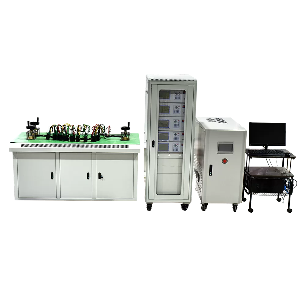
Unlike a CT test bench, which integrates measurement equipment, load equipment, and multiple testing stations for batch verification, a portable CT tester is generally designed for individual transformer testing and field applications.
How Does a CT Tester Work?
Although the internal design varies between manufacturers and models, a modern CT tester generally follows three main stages: applying a test signal, measuring electrical responses, and processing the collected data.
Applying a Test Signal to the CT
The first stage is generating a controlled electrical signal for the selected test.
For many portable CT analyzers, the instrument connects to the CT secondary terminals and applies a controlled low-voltage signal. Depending on the selected function, this may be an AC excitation signal or a DC measurement current.
For example:
- Excitation testing uses an AC voltage signal to examine the relationship between voltage and excitation current.
- Winding resistance testing uses a DC measurement current to determine the winding resistance.
- Ratio and accuracy evaluation uses measured electrical characteristics and the instrument’s calculation method to determine the CT’s transformation performance.
The signal level and testing sequence depend on the instrument design and the selected test function. The tester controls the output to keep the measurement within its specified operating range.
Measuring Voltage and Current Signals
After applying the test signal, the instrument measures the electrical response of the CT.
Its measurement circuits collect voltage and current signals from the designated test connections. These signals provide the information required to evaluate the transformer’s electrical characteristics.
For example, during an excitation test, the tester records the applied voltage and corresponding excitation current at different measurement points. During resistance testing, it measures the voltage drop produced by a known DC current.
Accurate signal acquisition is essential because measurement errors at this stage can affect all subsequent calculations.
Processing Data and Calculating Results
The collected signals are transferred to the instrument’s internal processing unit for analysis.
Depending on the test function, the instrument may calculate:
- Transformation ratio and ratio error
- Phase displacement
- Winding resistance
- Excitation characteristics
- Saturation-related parameters
- Burden impedance
The tester then displays the calculated values or generates a curve for further evaluation. Some digital analyzers also compare the results with selected technical standards and store the test records.
This combination of controlled signal generation, electrical measurement, and data processing forms the basic working principle of a modern CT analyzer.
How Does a CT Tester Measure Different CT Parameters?
Different CT parameters require different measurement methods. Understanding these methods makes it easier to interpret the results produced by a CT tester.
CT Ratio Measurement
The transformation ratio describes the relationship between the primary and secondary rated currents of a CT.
The rated transformation ratio is calculated as:
Rated CT Ratio = Rated Primary Current / Rated Secondary Current
Where:
- Rated Primary Current is the rated current on the primary side.
- Rated Secondary Current is the rated current on the secondary side.
For example, a CT rated at 600/5 A has a nominal transformation ratio of 120.
A CT analyzer evaluates the actual transformation ratio using its supported measurement method and compares it with the rated value. The difference can be expressed as ratio error.
Ratio Error (%) = [(Rated Ratio – Actual Ratio) / Actual Ratio] × 100%
The measured ratio and error help determine whether the CT meets its specified accuracy requirements.
CT Excitation Characteristic Measurement
The excitation test evaluates the magnetic characteristics of the CT core.
During this test, the instrument applies an increasing AC voltage to the CT secondary winding and measures the corresponding excitation current. By recording multiple voltage-current points, it generates an excitation curve.
The curve helps engineers identify the knee-point region and understand how the core behaves as the applied voltage increases.Excitation testing is particularly important for protection CTs because their performance under high fault currents depends on their magnetic characteristics and saturation behavior.
A CT excitation testing analyzer can help evaluate these characteristics and provide relevant excitation data for further analysis.
CT Polarity and Phase Relationship Measurement
Polarity testing verifies the relationship between the primary and secondary terminal directions.
In a correctly connected CT, the polarity markings indicate the corresponding current reference directions. Incorrect polarity can affect metering readings and protection relay operation.
A CT tester evaluates polarity through the electrical response and phase relationship obtained during the test. Depending on the instrument, it may use an applied signal and the measured response to determine the polarity relationship.
Phase displacement measurement goes further by determining the angular difference between the primary and secondary current quantities.
These measurements are important when evaluating CT accuracy, especially in precision metering applications.
CT Winding Resistance Measurement
Secondary winding resistance testing checks the electrical resistance of the CT winding.
The basic measurement principle follows Ohm’s law:
Winding Resistance (R) = Measured Voltage (U) / Applied DC Current (I)
Where:
- (R) is winding resistance.
- (U) is the measured voltage drop.
- (I) is the applied DC current.
The tester applies a controlled DC current and measures the resulting voltage drop. It then calculates the winding resistance.
Resistance measurements can help identify abnormal winding connections or changes in the electrical condition of the winding. Temperature should also be considered when comparing measurements taken under different conditions.
What Happens Inside a Digital CT Tester?
Digital CT testers use electronic measurement and processing circuits to handle signals and calculate test results. Several internal functions work together to complete the measurement.
Signal Acquisition
The acquisition circuit receives the voltage and current signals from the test connections. These analog signals are converted into digital data for subsequent processing.
The quality of this stage affects the reliability of the measurement, particularly when the instrument needs to evaluate small phase differences or low-level current signals.
Digital Signal Processing
After conversion, the digital processing unit analyzes the collected data and performs the required calculations.
Depending on the instrument, the processing system may calculate ratio errors, phase displacement, resistance, and excitation characteristics. It can also organize the measurement data into curves and result tables.
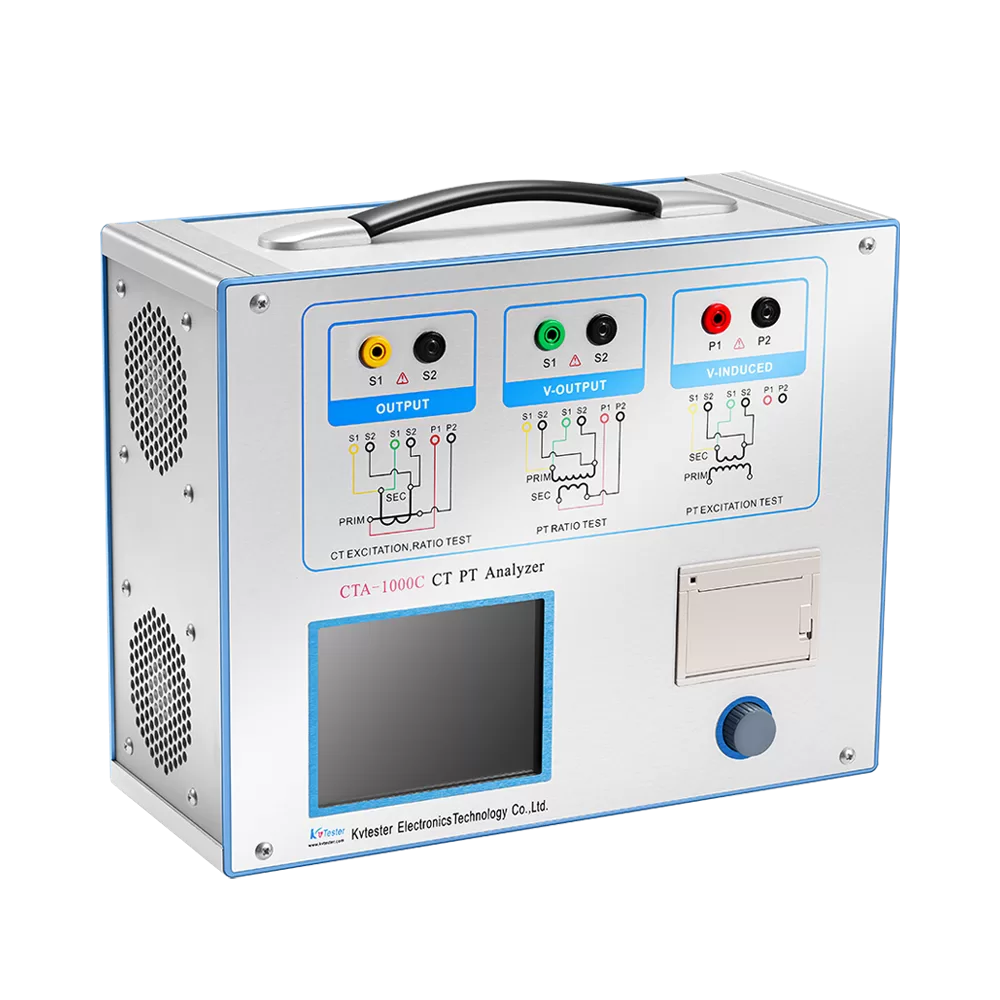
For example, the CTA-1000C uses digital processing technology and supports multiple CT measurement functions, including ratio, phase-angle accuracy, excitation characteristics, winding resistance, and burden measurement.
Automatic Measurement and Result Display
Some CT analyzers automatically perform a sequence of measurements after the operator selects the required test function and enters the relevant parameters.
The instrument processes the results and displays the corresponding values without requiring the operator to calculate every parameter manually.
For example, the CTA-1000D provides automatic CT evaluation, with a specified automatic test duration of less than two minutes under its supported testing conditions. Its results can be evaluated according to selected IEC or IEEE standards.
What Factors Affect CT Tester Measurement Accuracy?
Even when a CT tester uses advanced measurement and processing technology, the final results depend on the complete testing setup.
Test Lead Connections
Incorrect terminal connections, loose contacts, or damaged test leads can affect measurement results. Before testing, confirm the terminal markings and follow the wiring diagram for the selected function.
Test Signal Stability
The applied signal must remain within the instrument’s specified operating conditions. Unstable output or unsuitable test settings may influence the measurement.
Parameter Configuration
Incorrect rated current, winding selection, or test conditions can lead to misleading results. Always verify the CT nameplate information before starting the test.
External Interference
Electromagnetic interference and unsuitable grounding arrangements may affect sensitive measurements, especially when testing in substations or industrial environments.
Instrument Measurement Capability
Different CT testers have different measurement ranges, output capabilities, resolutions, and accuracy specifications. Select an instrument that matches the CT characteristics and required testing standards.
For a more detailed discussion of wiring and connection checks, see our CT analyzer connection guide.
CT Tester vs. CT Test Bench: How Are They Different?
Although both devices are used for current transformer testing, they serve different operational requirements.
A portable CT tester integrates measurement and analysis functions into one instrument. It is suitable for testing individual CTs during field maintenance, commissioning, or laboratory inspection.
A CT test bench combines measurement instruments, programmable loads, power supplies, control systems, and testing stations. It is designed for more structured testing workflows, particularly in CT manufacturing and batch verification.
The choice depends on the testing environment, daily workload, and required level of automation.
Conclusion
The CT tester working principle involves three essential stages: applying a controlled test signal, measuring the electrical response, and processing the collected data to evaluate CT performance.
Different measurement functions use different principles. Ratio testing evaluates the transformation relationship, excitation testing examines the magnetic characteristics of the core, polarity testing checks the terminal relationship, and resistance testing measures the winding’s electrical resistance.
Understanding these processes helps engineers select suitable equipment and interpret test results more effectively. If you need a CT tester for field testing, laboratory inspection, or transformer manufacturing, contact Kvtester to discuss your measurement requirements and find an appropriate testing solution.
Related Products
Latest News
-
 2026-11-19Anti-interference Transformer Tester for Substation
-
 2026-11-19CT Test Bench for Automated Current Transformer Testing
-
 2026-11-19Variable Frequency CT Tester: Why Frequency Matters
-
 2026-11-13What testing instruments are required for the handover testing of 10kV transformers?
-
 2026-11-13Acceptance Testing Standards and Procedures for 10kV Distribution Transformers