Acceptance Testing Standards and Procedures for 10kV Distribution Transformers
Acceptance Testing Standards and Procedures for 10kV Distribution Transformers
10kV distribution transformers are widely used in industrial facilities, commercial buildings, substations, and power distribution projects. Before newly installed transformers are officially put into service, they must undergo acceptance testing in accordance with relevant standards. This process verifies the equipment’s insulation performance, electrical parameters, and installation quality, ensuring that the transformer can operate safely and reliably.
So, what are the required acceptance tests for 10kV distribution transformers, and how should they be performed?
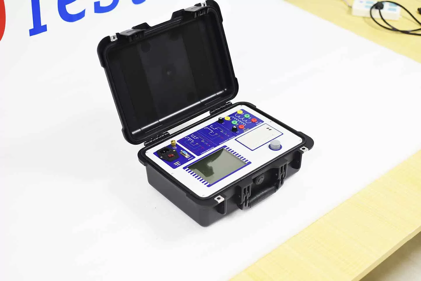
1. Basis for 10kV Distribution Transformer Acceptance Testing
Currently, on-site acceptance testing for distribution transformers is primarily governed by the national standard GB 50150-2016, “Standard for Handover Test of Electric Equipment in Electrical Installation Engineering.”
Chapter 8 of this standard outlines the specific acceptance tests and technical requirements for power transformers. In practice, testing should also take into account the transformer type, capacity, the manufacturer’s technical documentation, and the specific acceptance requirements of the local power utility.
2. Key Acceptance Tests for 10kV Distribution Transformers
①. DC Resistance Test of Windings
This test primarily checks the quality of connections and welds within the transformer windings, as well as the contact integrity of the tap changer.
Test Procedure: Using a transformer DC resistance tester, measure the DC resistance of each phase winding on both the high-voltage and low-voltage sides at specified tap positions, while recording the winding temperature.
Acceptance Criteria: For three-phase transformers rated at 1600 kVA or below, the difference in resistance between phases should not exceed 4%. For windings without a neutral point, the difference in line-to-line resistance should not exceed 2%. Furthermore, the measured values should not deviate by more than 2% from the factory-recorded values (adjusted for the same temperature).
②. Voltage Ratio and Vector Group (Connection Group) Test
This test verifies that the transformer’s voltage ratio, tap positions, and the connection configuration (vector group) of the three-phase windings conform to the design specifications. Test Method: Using a transformer turns-ratio and vector-group tester, connect the corresponding test terminals on the high-voltage and low-voltage sides. Measure the turns ratio at each tap position and verify the vector group designation.
Acceptance Criteria: For transformers with a voltage rating below 35 kV and a voltage ratio of less than 3, the allowable deviation for the voltage ratio is ±1%. For other transformers, the allowable deviation at the rated tap position must not exceed ±0.5%. The values at all other tap positions must also comply with the relevant standards.
③. Insulation Resistance Test
This test primarily assesses the insulation performance between the high-voltage and low-voltage windings, as well as between the windings and the ground.
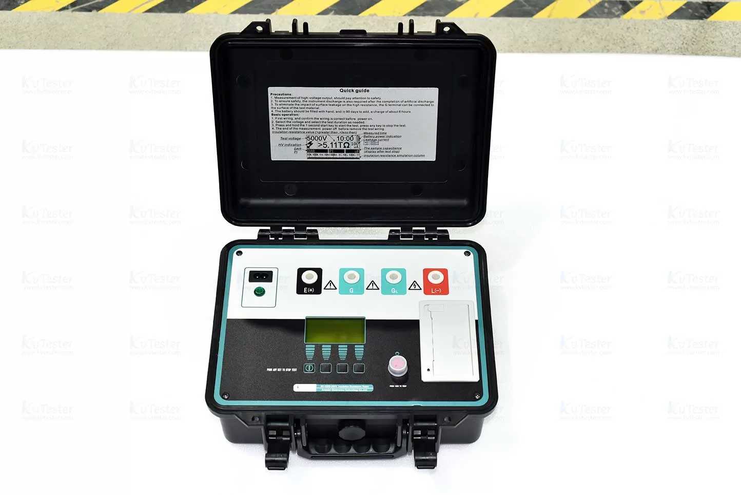
Test Method: Using a digital insulation resistance tester, measure the insulation resistance between the high-voltage side and ground, the low-voltage side and ground, and between the high-voltage and low-voltage windings. Record the measured values at the specified time intervals, along with the temperature.
Acceptance Criteria: In accordance with Article 8.0.10 of GB 50150-2016, compare the results against the manufacturer’s factory test data and applicable standards. The insulation resistance should not be less than 70% of the manufacturer’s factory test value, nor less than 10,000 MΩ (at 20°C). The final assessment should take into account the specific applicable clauses and temperature-based corrections.
④. Insulation Resistance Test for Transformer Core and Clamping Components
This test primarily checks the insulation status between the transformer core, the clamping components, and the ground.
Test Method: Following installation, use a 2500 V megohmmeter to measure the insulation resistance between the core and ground, the clamping components and ground, and between the core and the clamping components. The test should be conducted for 1 minute; no flashover or breakdown should occur.
⑤. AC Withstand Voltage Test
The AC withstand voltage test is primarily used to verify the electrical strength of the transformer’s main winding insulation.
Test Method: Based on the transformer’s insulation level and Appendix D of GB 50150-2016, select the appropriate test voltage and perform the test using a power-frequency withstand voltage test apparatus. For transformers with a nominal system voltage of 10 kV and a maximum equipment voltage of 12 kV, the standard-specified AC withstand voltage is 28 kV; this applies to both oil-immersed and dry-type transformers. Once the specified test voltage is reached, it must be maintained for a duration of typically 1 minute, during which no breakdown or flashover should occur.
⑥. Insulating Oil Testing and Other Items
For oil-immersed transformers, the performance of the insulating oil must also be tested in accordance with the relevant test categories and acceptance requirements.
Additionally, depending on the equipment type and applicable requirements, other procedures should be performed, such as inspection of the on-load tap changer, impulse energization tests at rated voltage, phase verification, and inspection of related accessories.
3. Operational Workflow for 10 kV Distribution Transformer Handover Testing
To ensure the accuracy of test data, it is recommended to follow this workflow:
① Pre-test Preparation: Verify the transformer nameplate, technical documentation, and factory test reports; inspect the equipment’s external condition, wiring, and grounding.
② Safety Isolation: Confirm that the equipment is de-energized; implement measures for voltage verification, discharging, grounding, and safety isolation.
③ Electrical Parameter Testing: Sequentially perform tests for DC resistance, voltage ratio, and vector group (connection group) designation.
④ Insulation Performance Testing: Measure the insulation resistance of the windings, as well as that of the core and clamping structures.
⑤ Withstand Voltage Testing: Conduct an AC withstand voltage test at the specified voltage and for the required duration.
⑥ Data Compilation: Analyze the test results by comparing them against standards, design specifications, and factory data, then compile a comprehensive handover test report.
4. What Equipment Is Required for 10 kV Distribution Transformer Handover Testing?
Power testing organizations and distribution project contractors may configure their equipment based on specific testing needs, including:
① Transformer DC resistance tester;
② Transformer turns ratio and vector group tester;
③ Insulation resistance tester (2500V or other appropriate specification);
④ Power-frequency withstand voltage test set;
⑤ Insulating oil dielectric strength tester (for oil-immersed transformers). 5. Conclusion
Handover testing for 10kV distribution transformers is a critical quality inspection step prior to commissioning. By conducting tests—such as DC resistance, turns ratio, insulation resistance, and AC withstand voltage—in a standardized manner, any quality issues that may have arisen during the transportation or installation of the transformer can be identified in a timely fashion.
Selecting appropriate electrical testing equipment and strictly adhering to national standards and safety operating procedures are essential foundations for ensuring the safe commissioning of distribution transformers.
Related Products
Latest News
-
 2026-11-13What tests are required for the grid-connection acceptance of distribution transformers?
-
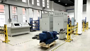 2026-11-13What Key Parameters Should Be Evaluated When Purchasing a Transformer Comprehensive Test Bench?
-
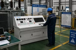 2026-11-13How Do Integrated Transformer Test Benches Improve Factory-Gate Testing Efficiency?
-
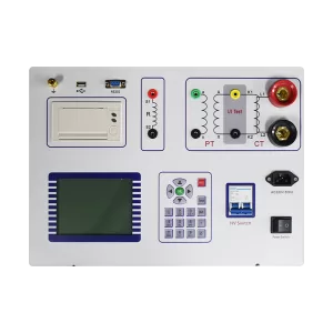 2026-11-12PT Tester User Manual for Setup, Wiring and Testing
-
 2026-11-12CT PT Analyzer Excitation Testing for CT and PT Evaluation