Home » News » Company News
CT PT Analyzer Excitation Testing for CT and PT Evaluation
Current transformers (CTs) and voltage transformers (PTs) both rely on magnetic cores to perform their electrical measurement functions. The magnetic characteristics of these cores influence how accurately a transformer responds to changing electrical conditions. Excitation testing helps engineers examine this behavior by measuring the relationship between applied voltage and excitation current.
Although CT and PT excitation tests share a similar measurement principle, their purposes and evaluation criteria are not identical. CT excitation testing often focuses on core saturation and protection performance, while PT excitation testing examines the magnetic behavior of the electromagnetic unit.
A CT PT Analyzer can perform these tests without requiring separate conventional test arrangements for every measurement. Understanding what each test evaluates makes it easier to select suitable equipment and interpret the results.
Why Do CTs and PTs Need Excitation Testing?
The magnetic core is an important part of both current and voltage transformers. When the core operates under different magnetic conditions, its excitation current changes accordingly. An excitation test helps engineers observe this relationship and identify characteristics that may affect transformer performance.
For CTs, excitation testing is particularly important when evaluating protection and metering applications. A protection CT must reproduce primary current accurately during fault conditions. If its core enters saturation too early, the secondary current may become distorted, potentially affecting the operation of connected protection devices.
For PTs, excitation testing focuses on the magnetic behavior of the electromagnetic unit. Abnormal excitation characteristics may indicate changes in the core or winding condition. The results can therefore support equipment inspection and condition assessment.
Excitation testing is useful in several situations:
- Manufacturing inspection: Checking magnetic characteristics during transformer production.
- Acceptance testing: Verifying relevant performance characteristics before equipment is put into service.
- Maintenance: Identifying changes in excitation behavior during periodic inspections.
- Troubleshooting: Investigating unexpected measurement or transformer performance issues.
The test results should always be evaluated alongside the transformer’s rated parameters, design requirements, and applicable testing standards.
How Does CT Excitation Testing Work?
CT excitation testing evaluates the relationship between the voltage applied to the secondary winding and the resulting excitation current. It provides information about the magnetic characteristics of the CT core, particularly its behavior as the applied voltage increases.
Measuring the CT Excitation Curve
During the test, the CT primary circuit is kept isolated, and an AC test voltage is applied to the secondary winding. The analyzer gradually changes the applied voltage and measures the corresponding excitation current.
The collected measurements are used to generate an excitation curve, also called a volt-ampere characteristic curve.
The curve normally shows:
- Applied excitation voltage on the vertical axis.
- Excitation current on the horizontal axis.
- The relationship between voltage and current as the magnetic core becomes increasingly magnetized.
At lower excitation levels, the current generally increases gradually as the applied voltage rises. As the core approaches saturation, a relatively small voltage increase can produce a much larger increase in excitation current.
This change in curve behavior provides useful information about the CT’s magnetic characteristics. For engineers who need a broader understanding of CT testing and result interpretation, our guide to CT analyzer testing and test result evaluation explains how excitation measurements fit into the overall CT assessment process.
Understanding Knee Point Voltage and CT Saturation
Knee Point Voltage is one of the important parameters obtained from CT excitation testing, especially for protection CT applications.
It represents a characteristic point on the excitation curve where the core begins to enter a more pronounced saturation region. Beyond this point, a relatively small increase in applied voltage can cause a significant increase in excitation current.
Why does this matter?
During a power system fault, a protection CT may need to reproduce a much higher primary current than it normally carries. If the core saturates under the required operating conditions, the secondary current may no longer accurately represent the primary current.
The knee point therefore helps engineers assess the CT’s ability to maintain its intended magnetic performance under demanding conditions.
However, there is no single knee point voltage suitable for every CT. The required value depends on the CT design, protection application, system conditions, and applicable standards. Engineers should compare the measured result with the relevant design and acceptance requirements rather than relying on a universal threshold.
How Is PT Excitation Testing Different from CT Testing?
PT excitation testing is also available, but it should be understood in the context of the PT’s electromagnetic structure and application.
Unlike a CT, which transforms current, a PT transforms voltage. Its excitation characteristics are related to the magnetic behavior of the voltage transformer’s core under the applied test voltage.
What Does a PT Excitation Test Measure?
For an electromagnetic PT, excitation testing examines the relationship between the voltage applied to the winding and the resulting excitation current.
The analyzer measures how the current changes as the applied voltage increases. This information helps engineers observe the magnetic characteristics of the PT electromagnetic unit and identify unusual behavior.
The test can be useful during manufacturing inspection, acceptance testing, and maintenance. For example, if the measured excitation behavior differs significantly from expected characteristics or previous results, engineers may need to investigate the winding, core, test connections, or other relevant conditions.
The purpose is not simply to obtain a knee point value in the same way as a protection CT assessment. Instead, the focus is on evaluating the excitation characteristics of the PT electromagnetic unit.
Why Should PT Results Be Evaluated Differently?
CT and PT excitation tests use a related voltage-current measurement principle, but their results serve different engineering purposes.
For CTs, engineers often pay particular attention to the excitation curve, knee point voltage, and saturation behavior. These characteristics are closely related to the CT’s ability to reproduce current during normal and fault conditions.
For PTs, the evaluation focuses more broadly on the excitation behavior of the electromagnetic unit. The measured curve should be considered in relation to the PT’s rated voltage, winding configuration, design characteristics, and relevant acceptance criteria.
It is also important to distinguish electromagnetic PTs from capacitive voltage transformers (CVTs). A CVT uses a capacitive voltage divider and has a different structure. Its voltage ratio and error testing requirements should not be confused with the excitation testing of an electromagnetic PT.
Therefore, when selecting a CT PT Analyzer, users should confirm that the instrument explicitly supports excitation testing for the required transformer type.
How Does a CT PT Analyzer Perform Excitation Testing?
A CT PT Analyzer combines controlled voltage output, measurement, data processing, and result presentation in one instrument. Instead of relying entirely on separate test equipment and manual calculations, engineers can use the analyzer to collect and evaluate excitation data.
The general testing process involves several stages.
Connecting the test circuit
The analyzer is connected to the relevant transformer winding according to the manufacturer’s wiring instructions. For CT excitation testing, the test is generally performed from the secondary side with the primary circuit isolated.
Applying the test signal
The instrument applies a controlled AC test voltage. Depending on the analyzer’s design, it may use a variable-frequency method to obtain the required excitation characteristics.
Measuring excitation current
As the test voltage changes, the analyzer measures the corresponding excitation current. These measurements provide the data needed to describe the magnetic response of the core.
Generating the excitation curve
The collected voltage and current values are processed to produce the excitation curve. This allows engineers to observe the core’s behavior across the test range.
Calculating relevant parameters
Depending on the instrument and selected test configuration, the analyzer may automatically calculate parameters such as knee point voltage and current, error curves, ALF, FS, and other CT-related characteristics.
Automated calculation helps reduce manual work and makes it easier to organize test results. However, automatic results still need to be reviewed against the correct transformer type, nameplate information, and applicable evaluation criteria.
When evaluating an analyzer, we recommend checking its supported CT and PT types, excitation output capability, measurement range, automatic calculation functions, and data storage options. These details are more useful than choosing equipment based only on the number of functions advertised.
What Should You Check in CT and PT Excitation Test Results?
An excitation curve provides useful information, but engineers should not evaluate every transformer using exactly the same criteria. The first step is to identify whether the test concerns a CT or an electromagnetic PT.
Key Results for CT Excitation Testing
For CTs, several results deserve attention:
- Excitation curve: Check the overall shape and whether the voltage-current relationship is consistent with the expected magnetic behavior.
- Knee point voltage and current: Review the calculated values in relation to the CT’s design and intended application.
- ALF (Accuracy Limit Factor): Consider this parameter when evaluating applicable protection CT performance.
- FS (Instrument Security Factor): Review it when assessing the relevant metering CT characteristics.
- Other calculated parameters: Depending on the CT class and test method, results may include error curves, secondary time constant (Ts), remanence coefficient (Kr), and saturated or non-saturated inductance.
Not every parameter applies to every CT. For example, ALF and FS are associated with different CT applications, so engineers should select the relevant evaluation criteria rather than treating all calculated values as universal acceptance indicators.
Key Results for PT Excitation Testing
For electromagnetic PTs, engineers should focus on the measured excitation voltage-current relationship and the overall curve behavior.
The results should be compared with the PT’s rated information, design specifications, previous measurements where available, and applicable testing requirements.
If an unexpected result appears, it is important to check the test connections, winding selection, entered parameters, and instrument setup before concluding that the PT has a core or winding problem.
In both CT and PT testing, an excitation result is one part of a broader condition assessment. It should be considered together with other relevant measurements, such as winding resistance, ratio, polarity, and burden.
Choosing a CT PT Analyzer for Both CT and PT Testing
If your testing work involves both current and voltage transformers, choosing an analyzer that supports the required excitation tests can simplify equipment management. At Kvtester, we offer several CT/PT analyzers for different testing requirements.
CTA-1000D CT/PT Analyzer
Our CTA-1000D CT/PT Analyzer supports CT excitation and saturation testing, as well as PT excitation and saturation testing. It also provides functions for ratio and phase-angle accuracy, winding resistance, burden impedance, polarity, and inductance measurement.
The instrument has a maximum output voltage of 120 V and an output current of up to 5 A RMS, with a 15 A peak output. Its automatic testing functions make it a practical option for teams that need to evaluate multiple CT characteristics and perform supported PT tests with one instrument.
CTA-1000C CT/PT Analyzer
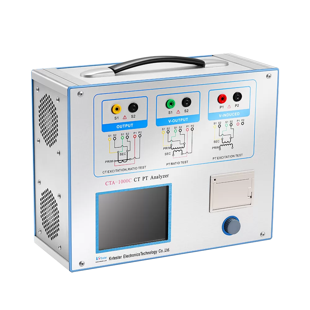
The CTA-1000C CT/PT Analyzer supports CT excitation characteristics and PT excitation and saturation testing. It also covers ratio, polarity, secondary winding resistance, and burden measurements.
Its output capability reaches 180 Vrms, 12 Arms, and 36 A peak. The CT ratio measurement range is 1–40,000, with a stated accuracy of ±0.05%. This combination of measurement functions makes it suitable for users who need a comprehensive instrument for CT and PT testing.
The right choice depends on the CT and PT types you test, the required excitation range, and the other measurements needed in your daily work. We recommend checking the complete specifications and confirming compatibility with your actual testing requirements before selecting a model.
Conclusion
Excitation testing provides valuable information about the magnetic characteristics of both current transformers and electromagnetic voltage transformers. For CTs, the main concerns often include excitation curves, knee point voltage, and saturation behavior. For PTs, the test helps evaluate the excitation characteristics of the electromagnetic unit.
A suitable CT PT Analyzer should support the transformer types you need to test and provide sufficient measurement capability for your application. If you are selecting equipment for CT and PT excitation testing, contact Kvtester to discuss your requirements and identify an appropriate testing solution.
Related Products
Latest News
-
 2026-11-12PT Tester User Manual for Setup, Wiring and Testing
-
 2026-11-12CVT PT Tester for Accurate Voltage Transformer Testing
-
 2026-11-12Testing Large Power Transformers with a Short Circuit Impedance Tester
-
 2026-11-11Digital CT PT Analyzer for Smarter Transformer Testing
-
 2026-11-11CT PT Analyzer Polarity Test for Accurate CT and PT Verification