What is the basic principle of partial discharge testing?
What is the basic principle of partial discharge testing?
Partial discharge (PD) testing is a critical diagnostic procedure for assessing the insulation of high-voltage electrical equipment, primarily used to identify localized defects within or on the surface of the insulation. Unlike a complete insulation breakdown, a partial discharge occurs only in a specific, localized area of the insulation system. While it does not immediately result in a full-scale, bridging discharge, its persistent, long-term presence can lead to the gradual degradation of the insulation, ultimately compromising the operational safety of the equipment.
PD testing can be used to help determine whether internal defects—such as air gaps, impurities, or points prone to corona discharge—exist within the insulation of equipment such as transformers, cables, instrument transformers, gas-insulated switchgear (GIS), and high-voltage motors.
1. What is a partial discharge?
A partial discharge occurs when the electric field strength in a localized region of the insulation within high-voltage equipment exceeds the withstand capacity of that specific area.
For instance, if a tiny air gap exists within solid insulation, the air—which typically has a lower dielectric strength than the surrounding solid material—may undergo electrical discharge first when subjected to an AC voltage.
Because this discharge is confined to a portion of the insulation and does not fully bridge the two electrodes, it is termed a “partial discharge.” Although the energy released by a single discharge event is generally small, repeated occurrences over time can progressively damage the insulating material, potentially creating carbonized tracks or enlarging existing defects.
2. How does partial discharge testing detect these discharges?
When a partial discharge occurs, it generates a very short-duration pulse current, accompanied by physical phenomena such as electromagnetic waves and acoustic signals. Conventional electrical PD testing methods detect these high-frequency pulse signals to identify discharge activity.
During testing, a specified AC test voltage is applied to the equipment under test. If a partial discharge occurs internally, it triggers an instantaneous charge transfer, which manifests as a high-frequency pulse signal within the test circuit. By using coupling capacitors, detection impedances, and a partial discharge analyzer, these pulse signals can be captured, amplified, filtered, and processed to derive test results, such as the magnitude of the partial discharge. In simple terms, the entire process can be summarized as follows: applying a test voltage → generating partial discharges (PD) at insulation defects → creating high-frequency pulses → capturing these signals via a test system → analyzing the discharge magnitude and characteristics.
3. What is “partial discharge magnitude”?
A common parameter in partial discharge testing is “apparent charge,” typically expressed in picocoulombs (pC). Apparent charge does not represent the total actual charge released within a defect; rather, it is a measured value derived from the charge change observed at the terminals of the test object via an external measurement circuit.
Generally, under identical equipment and test conditions, a higher discharge magnitude indicates more significant partial discharge activity. However, when assessing the insulation status of equipment, one should not rely solely on a pC value. Instead, a comprehensive analysis is required—incorporating factors such as the discharge inception voltage, extinction voltage, phase-resolved discharge patterns, repetition rate, and trends observed as the voltage varies.
4. Why is partial discharge testing susceptible to interference?
Partial discharge signals are inherently very weak, while the field environment often contains significant electromagnetic interference.
Sources such as switching power supplies, corona discharges, wireless communication equipment, poor grounding, or pulses generated by the operation of other high-voltage equipment can be mistakenly identified as partial discharges by the test system.
Consequently, partial discharge testing places high demands on grounding, shielding, the layout of test leads, and interference mitigation. If background noise is excessive, the source of the interference must first be identified. Mitigation strategies—such as improving grounding, adjusting the test circuit, adding shielding, or employing filtering and digital recognition techniques—should then be applied to reduce interference and prevent external noise from being misidentified as internal equipment discharge.
5. What types of insulation issues can be detected through partial discharge testing?
Partial discharge testing is primarily used to identify localized weak points within an insulation system, such as internal air gaps, impurities within insulating materials, discharges from sharp points or floating potentials, surface discharges, or abnormal discharges resulting from poor electrical contact. Therefore, the value of partial discharge (PD) testing extends beyond merely determining whether or not a discharge is occurring; by analyzing discharge amplitude, phase, and patterns, it provides insights into the type and severity of defects.
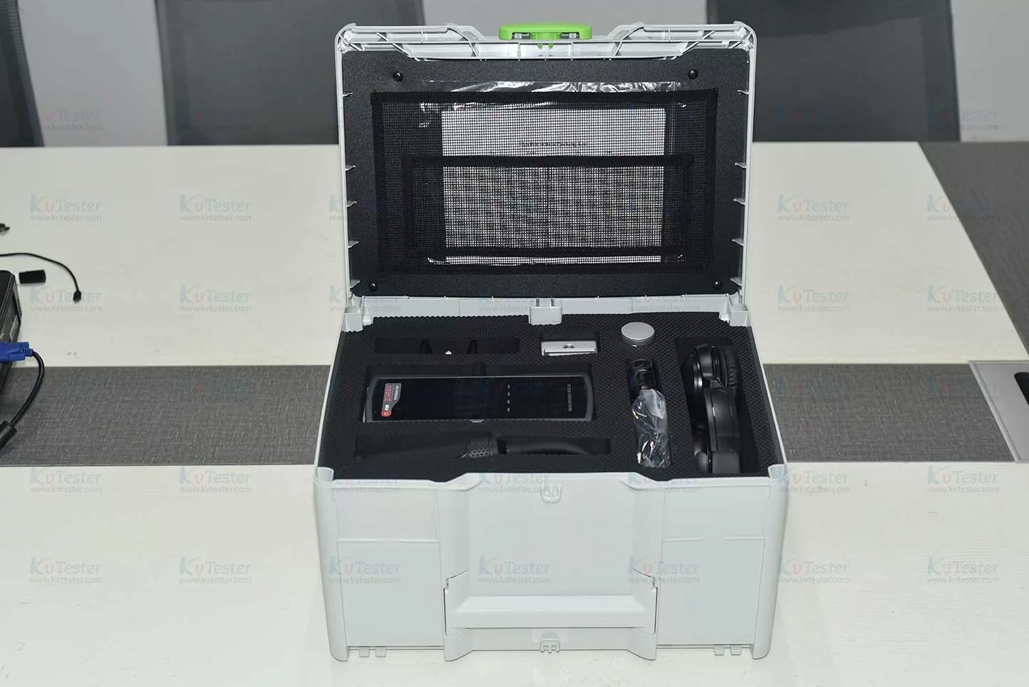
Summary
The fundamental principle of partial discharge testing involves applying a specified test voltage to the equipment under test and detecting high-frequency pulse signals generated by partial discharges within the insulation. Through the measurement and analysis of these signals, one can determine whether localized defects exist within the equipment’s insulation. Compared to traditional insulation resistance or withstand voltage tests, partial discharge testing is more effective at identifying localized weak points within the insulation. In practice, assessments should be based on a comprehensive analysis that considers factors such as discharge magnitude, inception voltage, phase characteristics, and background interference.
Related Products
Latest News
-
 2026-10-28Compact Portable Transformer Tester for Field Testing
-
 2026-10-28Intelligent CT Tester for Accurate Current Transformer Testing
-
 2026-10-27Combined CT PT Tester for Current and Voltage Transformer Testing
-
 2026-10-27IEC Standard Custom Transformer Tester for Reliable Testing
-
 2026-10-27Current Transformer Testing Equipment: Types & Selection