Home » News » Company News
Current Transformer Testing Equipment: Types & Selection
Selecting current transformer testing equipment requires understanding the CT’s application, the parameters that need to be measured, and the testing environment. Engineers must determine whether they need to verify transformation ratio, polarity, excitation characteristics, or accuracy. The right equipment helps identify potential problems, improve testing efficiency, and support reliable metering and protection systems.
What Does Current Transformer Testing Equipment Measure?
Current transformer testing equipment evaluates the electrical characteristics of a CT to help verify its performance against specified requirements. The necessary measurements depend on whether the transformer is used for metering, protection, or another application.
Common test parameters include:
- Transformation ratio: Checks the relationship between primary and secondary current.
- Polarity: Verifies the relative direction of primary and secondary winding connections.
- Excitation characteristics: Evaluates the relationship between excitation voltage and current.
- Winding resistance: Helps identify abnormal resistance or winding connection issues.
- Phase-angle error: Assesses phase displacement between primary and secondary quantities.
- Secondary burden: Evaluates the electrical load connected to the CT secondary circuit.
Not every instrument measures all these parameters. Before selecting equipment, identify the tests required by the CT design, applicable standards, and intended use.
Common Types of CT Testing Equipment
Different instruments address different testing requirements. Understanding their functions helps you choose the right combination of equipment.
Multifunction CT Analyzers
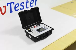
A CT analyzer combines several measurement functions in one instrument. Depending on the model, it may perform ratio, polarity, excitation, winding resistance, and burden tests.
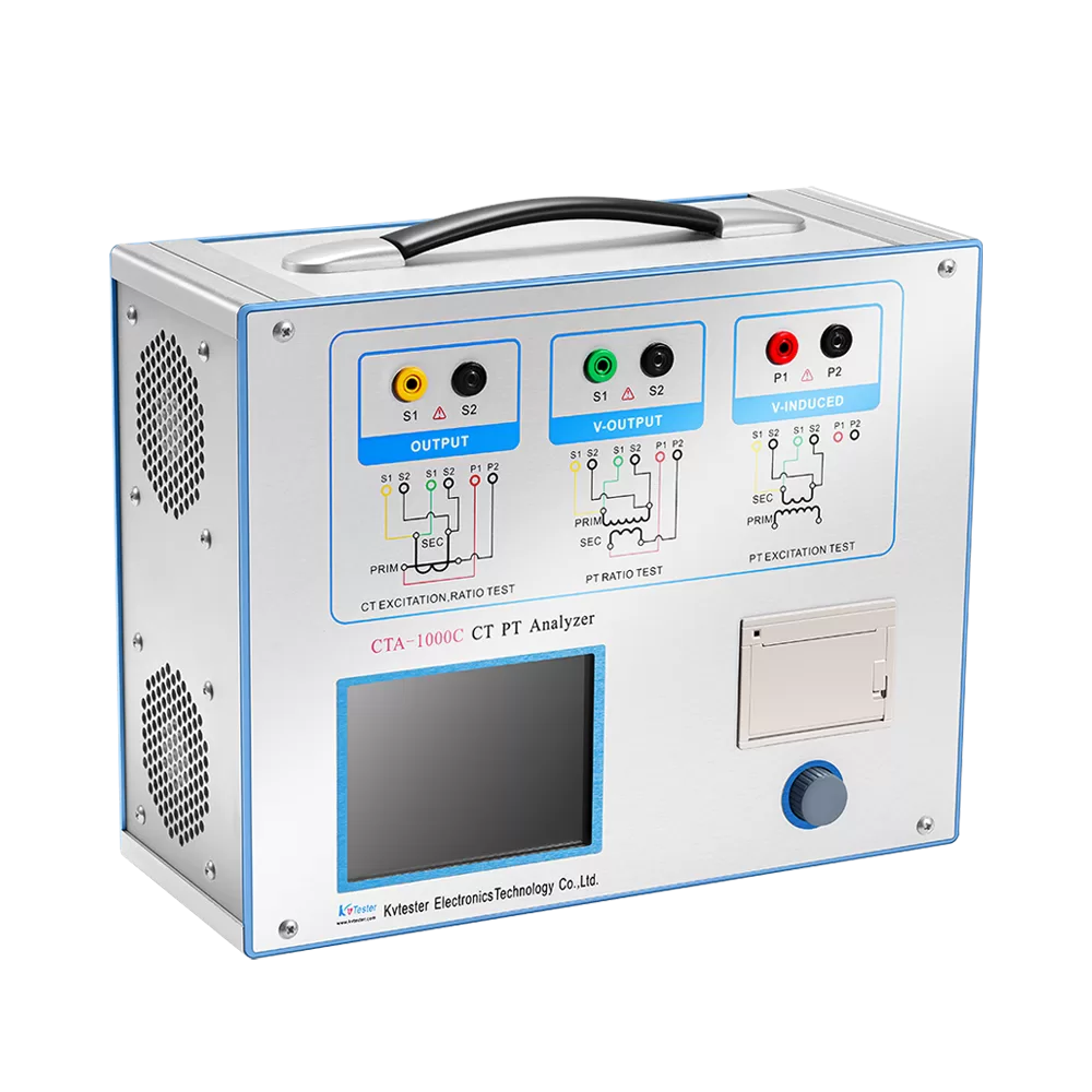
These instruments are useful when technicians need to evaluate multiple CT characteristics without connecting several separate devices. For example, the CTA-1000C CT/PT Analyzer supports CT ratio testing from 1 to 40,000, with a specified ratio accuracy of ±0.05%. Its DC resistance range is 0–300 Ω, and its burden measurement range is 0–1,000 VA.
Dedicated Testing Instruments
Dedicated instruments focus on specific measurements, such as winding resistance or primary current injection. They can be appropriate when a testing procedure requires a particular measurement or when an existing testing setup already covers the other parameters.
However, a resistance measurement alone cannot establish the CT’s overall accuracy or verify every aspect of its excitation performance. Select instruments according to the complete test procedure rather than a single parameter.
Automatic CT Testing Systems
Automatic systems integrate measurement, control, switching, and result management to support repeatable workflows. They are particularly useful in manufacturing facilities and laboratories where multiple CTs undergo similar tests.
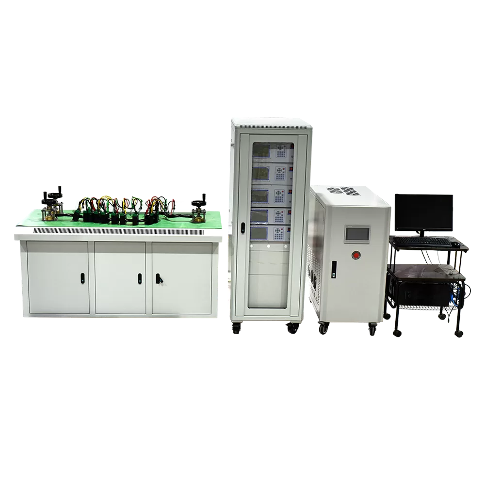
Our ZCHG-12 CT/PT Test System supports automatic CT accuracy testing, demagnetization, inter-turn insulation testing, and polarity checks. Its test bench can handle up to 12 CTs at one time, making it suitable for higher-volume testing requirements.
Essential Current Transformer Testing Methods
Understanding the purpose of each test helps determine which functions your equipment must provide.
Ratio and Polarity Testing
The ratio test checks whether the measured transformation ratio corresponds to the specified ratio. An unexpected result may indicate an incorrect connection, winding problem, or other issue requiring further investigation.
Polarity testing verifies terminal relationships. Correct polarity is important when CTs are connected to metering instruments, protective relays, or differential protection circuits.
Excitation Curve and Knee-Point Testing
An excitation test measures the relationship between applied secondary voltage and excitation current. The resulting curve provides information about the magnetic behavior of the CT core.
For protection applications, the knee-point voltage can be an important parameter. It helps characterize the point at which a relatively small increase in voltage produces a substantial increase in excitation current. Interpretation and acceptance criteria depend on the CT specification and applicable standard.
Winding Resistance and Burden Measurement
Winding resistance testing helps identify abnormal resistance values that may be associated with winding or connection problems. Temperature effects should be considered when comparing measurements.
Burden testing evaluates the load connected to the CT secondary circuit. Excessive burden can affect CT performance, so the connected instruments, wiring, and total circuit impedance should be considered together.
Accuracy and Phase-Error Evaluation
For metering applications, ratio error and phase displacement can affect measurement accuracy. Equipment selection should therefore account for the required accuracy class and test conditions rather than relying on ratio measurement alone.
How CT Testing Equipment Supports Different Applications
Testing requirements vary across utilities, manufacturing facilities, and calibration laboratories.
- Power utilities and substations: Field testing helps verify CT characteristics during commissioning, maintenance, and troubleshooting.
- CT manufacturers: Factory inspections help check product performance during production and before delivery.
- Calibration laboratories: Measurement accuracy, repeatability, and documentation are important for controlled testing procedures.
- Testing service providers: Portable instruments help technicians perform measurements at different locations without transporting every CT to a laboratory.
For field maintenance, portability and straightforward operation can be priorities. In manufacturing, automation, repeatability, and batch-testing capacity may be more important.
For more information about equipment configurations and testing workflows, see our guide to CT/PT test system testing methods and equipment selection.
How to Choose Current Transformer Testing Equipment
A suitable purchasing decision should be based on measurable requirements rather than the number of functions advertised.
Confirm Test Coverage and Measurement Range
List the required measurements, then compare the instrument’s supported functions and ranges with the CTs being tested. Check current ratios, resistance range, excitation requirements, burden range, and accuracy specifications where relevant.
A multifunction analyzer may be sufficient for routine inspections. A more specialized or integrated system may be necessary when testing procedures involve additional functions or a high volume of units.
Check Standards and Test Procedures
Determine whether your work follows IEC, IEEE, or another applicable standard. Verify that the equipment supports the required test method and acceptance criteria.
A device that performs ratio and polarity tests may not cover every requirement for CT accuracy verification or insulation testing. Confirm the required functions before making a purchasing decision.
Consider Automation and Result Management
Automatic test sequences can reduce repetitive manual operations and improve consistency. For manufacturing and calibration work, check whether the equipment can store results, generate reports, and manage records for different CT specifications.
Evaluate Safety and Operating Conditions
Check the required connections, grounding arrangements, isolation requirements, and operating instructions. CT secondary circuits require particular care: a CT secondary must not be left open-circuited while primary current is flowing.
The equipment should also suit the working environment, whether it is used in a substation, laboratory, or production facility.
Common Mistakes When Testing Current Transformers
Even suitable equipment can produce misleading results if the testing procedure is incorrect.
- Using the wrong test method: A ratio test cannot replace an excitation test or a complete accuracy assessment.
- Ignoring secondary burden: The connected load and wiring can affect CT performance.
- Overlooking temperature effects: Winding resistance comparisons should account for temperature differences.
- Applying incorrect acceptance criteria: Interpret results using the relevant CT specification and applicable standard.
- Treating one test as a complete diagnosis: Abnormal results may require additional tests to identify the underlying cause.
A consistent procedure, correct connections, and appropriate interpretation are essential for reliable results.
Conclusion
Current transformer testing equipment should be selected according to the CT’s application, the required measurements, and the testing environment. Ratio, polarity, excitation, winding resistance, burden, and accuracy checks each provide different information about CT performance.
By defining the required test coverage and checking measurement ranges, standards, safety requirements, and reporting functions, engineers can choose equipment that fits their workflow without paying for unnecessary capabilities. The best solution is the one that reliably meets the actual testing requirements.
Related Products
Latest News
-
 2026-10-27Combined CT PT Tester for Current and Voltage Transformer Testing
-
 2026-10-27IEC Standard Custom Transformer Tester for Reliable Testing
-
 2026-10-26IEC Standard CT Analyzer Supplier: Choosing the Right Equipment
-
 2026-10-26Multi-function CT Tester Wholesale: Supplier Guide
-
 2026-10-26Lightweight Transformer Tester Selection Guide