
How to Use a Dielectric Loss Tester: Basic Field Testing Procedures and Precautions
How to Use a Dielectric Loss Tester: Basic Field Testing Procedures and Precautions
Dielectric loss testers are primarily used to measure the dielectric loss factor (tanδ or tgδ) and capacitance of high-voltage electrical equipment; they are standard instruments for insulation testing on devices such as transformers, bushings, instrument transformers, and CVTs. When using them in the field, in addition to correctly configuring test parameters, special attention must be paid to grounding, wiring, the testing environment, and high-voltage safety.
The following outlines the basic procedures and common precautions for using dielectric loss testers in the field.
1. Conduct Pre-test Site Inspections
Before performing a dielectric loss test, first confirm that the equipment under test has been de-energized and that safety measures—such as isolation, voltage verification, discharging, and grounding—have been implemented in accordance with high-voltage testing safety protocols. Simultaneously, inspect the tester, power cords, high-voltage test leads, and measurement cables for damage, and ensure the instrument’s grounding terminal is reliably connected to the ground. Dielectric loss measurements have strict requirements regarding grounding and shielding; poor grounding can compromise the stability of test data and increase risks during field testing.
For equipment that has just been taken out of service, verify that the test object’s status and the testing conditions meet the requirements specified in relevant testing regulations.
2. Select the Wiring Method Based on the Test Object
Dielectric loss testing generally involves “normal connection” (positive connection) and “reverse connection” modes, as well as specific methods for specialized equipment.
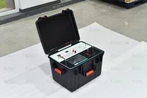
The choice of wiring method depends on the insulation structure of the equipment under test, the specific part being tested, and whether the equipment is directly grounded. For instance, testing methods may differ depending on whether the object is a transformer bushing, an instrument transformer, or a CVT. Therefore, relying solely on experience for wiring during field operations is not recommended; instead, confirm the wiring method by consulting the test object’s structural diagram, the test plan, and the instrument’s instruction manual. The ZC-221 Fully Automatic Anti-Interference Dielectric Loss Tester supports various testing modes—including normal connection, reverse connection, and CVT self-excitation—to meet the dielectric loss and capacitance testing needs of a wide range of high-voltage electrical equipment.
3. Set Test Voltage and Frequency
After completing and verifying the wiring, set the test voltage according to the test object and testing requirements. A higher test voltage is not necessarily better; the voltage should be selected appropriately based on the equipment type, rated parameters, and relevant testing standards. The ZC-221 offers selectable internal high-voltage outputs ranging from 0.5 kV to 10 kV, meeting the requirements for standard on-site dielectric loss testing. If significant power-frequency interference is present at the site, the test frequency can be adjusted to suit the actual environmental conditions.
4. Start the test and monitor the data
Once the wiring, grounding, and parameter settings have been verified, the test can be initiated following the instrument’s operating procedures. After the instrument ramps up the voltage and completes the measurement, data such as the test object’s tanδ (dissipation factor) and capacitance will be obtained. During the test, operators must maintain a safe distance from the high-voltage testing area and monitor the instrument for any error alerts, such as grounding faults or overcurrent conditions. Upon completion of the test, the high-voltage output must be terminated first, and the test object fully discharged in accordance with on-site testing requirements; only after safety is confirmed should the wiring be disconnected or the test object changed.
5. Do not rush to conclusions if test data appears abnormal
During on-site dielectric loss testing, instances of high tanδ values, data fluctuations, or significant discrepancies between repeated test results do not necessarily indicate an insulation fault in the equipment.
First, verify the instrument’s grounding and the correctness of the test lead connections and layout. Also, consider factors such as ambient humidity, surface contamination on the test object, and power-frequency interference from nearby operating equipment. Conducting repeat tests under identical conditions and performing a comprehensive analysis that incorporates the equipment’s historical data and results from other insulation tests is generally more reliable than relying solely on a single set of dielectric loss data.
Summary
The basic workflow for a dielectric loss tester can be summarized as follows: pre-test inspection, grounding verification, selection of wiring configuration, parameter setup, test initiation, data recording, and post-test discharging. On-site dielectric loss testing involves high-voltage operations and must be performed by qualified and experienced personnel in accordance with the equipment manual and relevant safety regulations. Proper wiring, appropriate parameter settings, and effective anti-interference measures are essential for obtaining stable and reliable dielectric loss test data.
Kvtester Electronics Technology Co.,Ltd. is a high-tech enterprise specializing in power testing, testing, research and development, production, and sales of testing equipment. It has been engaged in the electrical testing industry for many years, and its products are of high quality. We welcome customers to come and purchase. Service hotline: 0086-27-81778799, to learn more, visit the official website: www.kvtester.com
Related Products





Latest News
-
 2026-09-10What causes unstable or fluctuating dielectric loss test data?
 -
 2026-09-10What causes high dielectric loss values? Common causes and troubleshooting approaches
 -
2026-09-10What is the difference between the “normal connection” and “reverse connection” methods for dielectric loss testers?
-
 2026-09-10Working Principle and Main Applications of Anti-Interference Dielectric Loss Testers
 -
 2026-09-10PT Tester With Maintenance Service: Procurement Guide
