
How should 35kV cable series resonant withstand voltage test equipment be configured?
How should 35kV cable series resonant withstand voltage test equipment be configured?
35kV power cables are widely used in substations, renewable energy plants, industrial and mining enterprises, and power transmission and distribution projects. As cable length increases, so does the equivalent capacitance, placing higher demands on the current and capacity of AC withstand voltage test equipment. Consequently, variable-frequency series resonant systems are commonly used for on-site withstand voltage testing of 35kV cables. However, even for cables of the same 35kV rating, equipment configuration requirements can vary significantly between projects.
1. Why isn’t the 35kV rating alone sufficient for equipment selection?
While 35kV indicates the cable’s voltage rating, configuring series resonant equipment requires consideration of factors such as the actual test voltage, cable length, capacitance, and test frequency.
For instance, consider two cables with the same voltage rating: one is only a few hundred meters long, while the other spans several kilometers. Their total capacitance may differ greatly, resulting in different requirements for test current and reactor capacity.
Therefore, the 35kV rating serves only as a baseline condition for equipment selection, not the sole criterion.
2. Determine the maximum length for a single test first
For cable projects, the most critical factor is the maximum length to be tested in a single session.
It is important to distinguish between the project’s total cable length and the length of a single test segment. For example, if a project involves a total of 5 kilometers of cable made up of multiple sections, but the longest single section to be tested is only 800 meters, the equipment calculation should focus on that 800-meter scenario while factoring in other potential testing methods to determine the necessary safety margin. If there is a possibility of testing longer cables in the future, it is advisable to account for that requirement from the start.
3. Determine test current based on capacitance
A cable’s capacitive current depends on frequency, capacitance, and test voltage; this relationship can be approximated by the formula: I = 2πfCU.
At a given test voltage, the longer the cable and the higher the total capacitance, the greater the test current. This is why 35kV cable testing requires attention not only to output voltage but also to the reactor’s rated current. Even if the system can achieve the required voltage, the test cannot be successfully completed if the reactor’s permissible current is lower than the actual test current.
4. Checking the resonant frequency based on L and C
The series resonant frequency is determined by the formula: f = 1 / (2π√LC).
The system’s resonant frequency is jointly determined by the reactor inductance (L) and the capacitance (C) of the cable under test. When configuring equipment for a 35kV cable project, manufacturers adjust the equivalent inductance by connecting reactors in series or parallel; they then verify that the resonant frequency corresponding to various cable lengths falls within the equipment’s permissible operating range. Therefore, both “sufficient capacity” and “frequency coverage” must be evaluated simultaneously.
5. How are multi-section reactors combined?
A key advantage of modular series resonant systems is the flexibility of reactor combinations. Connecting reactors in series allows the system to withstand higher voltages, while parallel connections provide higher current capacity. By altering the connection configuration, a single set of equipment can accommodate test objects of varying lengths and capacitances.
This combinability is particularly important for users who need to perform tests on both 10kV and 35kV cables. With a well-designed system, a single set of equipment can cover multiple operating scenarios through reactor reconfiguration, eliminating the need to purchase separate systems for each voltage level.
6. Total equipment capacity is not the only evaluation metric
Series resonant equipment on the market is often labeled with a rating such as “XX kVA / XX kV.” However, two systems with identical total capacity ratings may differ significantly in terms of the number of reactor sections, voltage and current ratings per section, inductance values, and configuration methods. Consequently, procurement decisions should not be based solely on total kVA. It is more important to verify that the target cable can achieve resonance, the test voltage meets requirements, the current capacity is sufficient, the continuous operating time is suitable for field testing, and the individual equipment sections are convenient to transport.
7. What parameters are required for 35kV cable projects?
It is generally recommended to provide the cable model, voltage rating, cross-sectional area, maximum test length, capacitance per unit length (or total capacitance), and the maximum test voltage required by the project. If the equipment must also accommodate 10kV cables, cables of other lengths, or other types of test objects, this should also be specified. Specific withstand voltage values, frequency ranges, and test durations should be determined in accordance with the standards, regulations, and technical specifications applicable to the project. Users who do not yet have complete capacitance data need not simply purchase equipment based on standard model specifications derived from experience. Instead, by providing details such as the existing cable model, cross-sectional area, and length, the actual load can be calculated first; the configuration of the variable-frequency power supply, excitation transformer, reactor, and voltage divider can then be determined. For cable projects involving voltage levels of 35 kV or higher, this approach—selecting equipment based on specific operating conditions—is generally the more reliable method.
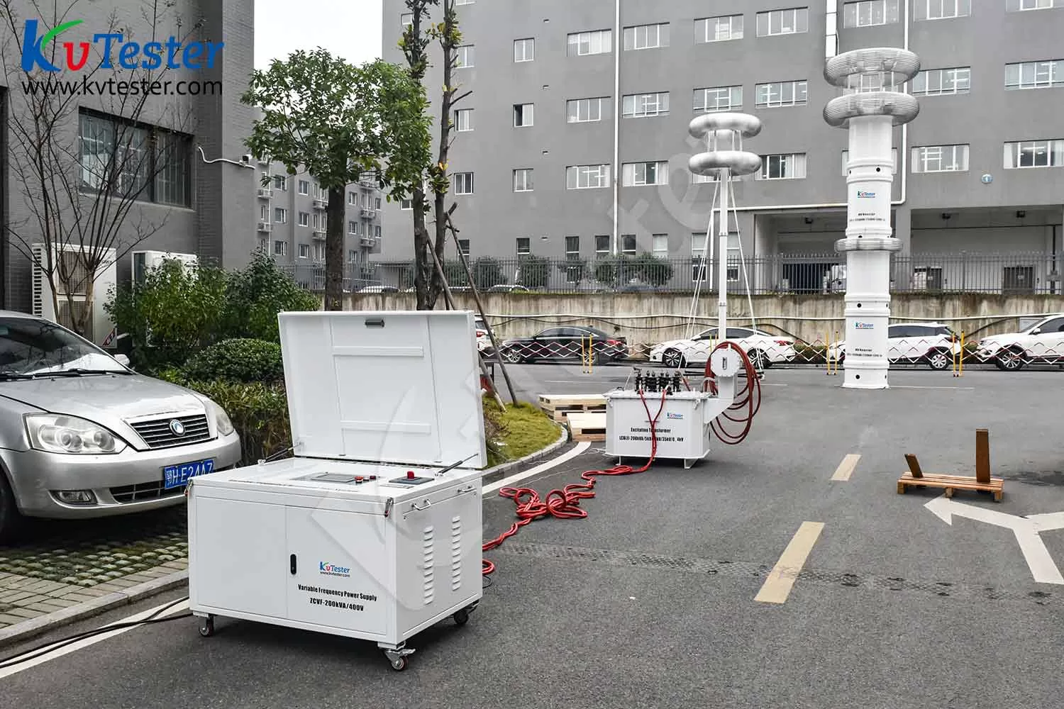
ZCVF-A series frequency conversion series resonant AC withstand voltage device is suitable for AC withstand voltage test of transformer, circuit breaker, switch, GIS system, cable, bushing, insulator and other equipment. It has the functions of high voltage over-voltage protection, low voltage over-current protection, detuning protection, zero position protection, flashover protection, emergency shutdown, under-voltage protection and so on. It not only meets the requirements of equipment test conditions for high voltage and small current, but also meets the requirements of equipment test conditions for low voltage and large current, and has a wide application range.
Kvtester Electronics Technology Co.,Ltd. is a high-tech enterprise specializing in power testing, testing, research and development, production, and sales of testing equipment. It has been engaged in the electrical testing industry for many years, and its products are of high quality. We welcome customers to come and purchase. Service hotline: 0086-27-81778799, to learn more, visit the official website: www.kvtester.com
Related Products





Latest News
-
 2026-09-18Why does the required capacity of series resonant test equipment usually increase with cable length?
 -
 2026-09-18How to Select AC Withstand Voltage Test Equipment for 10kV Cables?
 -
 2026-09-18What parameters must be provided to the manufacturer when purchasing series resonant withstand voltage test equipment?
 -
 2026-09-18How do you select a series resonant withstand voltage test system? Key parameters to consider
 -
 2026-09-18Multi-function Transformer Testing Equipment OEM Guide
