
How do you select a series resonant withstand voltage test system? Key parameters to consider
How do you select a series resonant withstand voltage test system? Key parameters to consider
Series resonant withstand voltage test systems are widely used for AC withstand voltage testing of electrical equipment such as power cables, GIS (Gas-Insulated Switchgear), transformers, and generators. For first-time buyers, the most common question is: “What capacity series resonant system do I need?” In reality, selection is not based solely on the voltage rating of the test object; beyond the test voltage, one must comprehensively consider parameters such as the test object’s capacitance, test frequency, test current, and the equipment configuration.
1. First, identify the type of test object
Electrical characteristics vary significantly among different test objects. Power cables are typical capacitive loads, and their total capacitance usually increases with cable length; meanwhile, equipment such as generators, GIS, and transformers have distinct equivalent capacitances and testing requirements. Therefore, the first step in selecting a series resonant system is not choosing a specific model, but clearly defining the primary test objects.
If the system is primarily intended for cable testing, you must further confirm the cable’s voltage rating, length, cross-sectional area, and capacitance (either per-unit-length or total). If a single system must accommodate multiple types of test objects, the configuration should account for the most demanding testing scenario likely to be encountered.
2. Determine the required maximum test voltage
The output voltage of the series resonant system must meet the maximum test voltage required by the actual project. It is important to note that the rated output voltage listed on the equipment nameplate does not mean that *all* test objects can be tested at that specific voltage.
The system’s actual output capability depends on factors such as the series/parallel combination of reactors, operating frequency, test current, and the capacitance of the test object. Consequently, determining the equipment configuration based solely on voltage ratings—such as “10kV cable” or “35kV cable”—is often inaccurate.
Specific test voltages and durations should be determined in accordance with applicable standards, regulations, and project technical specifications.
3. Test object capacitance is a crucial basis for selection
A series resonant system creates a resonant circuit using the inductance of the reactor and the capacitance of the test object. The resonant frequency is defined by the formula: f = 1 / (2π√LC), where L is the circuit inductance and C is the equivalent capacitance of the test object and the test circuit. When the capacitance of the test object changes, the corresponding resonant frequency also changes. Therefore, the equipment’s ability to locate the appropriate resonant point depends closely on the reactor’s inductance, the test object’s capacitance, and the operating frequency range of the variable-frequency power supply.
For power cables, if specific capacitance data is unavailable, an estimate can be made based on the capacitance per unit length provided by the manufacturer and the actual length of the cable to be tested.
4. Do not overlook the maximum test current
Capacitive loads generate capacitive current under AC voltage; the magnitude of this current can be approximated by the formula: I = 2πfCU.
This shows that for a given capacitance and test voltage, a higher test frequency results in a higher current; similarly, if the cable length increases—thereby increasing the capacitance—the test current will also rise.
Consequently, when selecting series resonant equipment, one must consider not only the maximum voltage output capability but also the reactor’s rated current capacity. Even if the voltage meets requirements, the test cannot be completed if the current rating is insufficient.
5. Reactor configuration is also crucial
Modular series resonant systems typically consist of multiple reactor units. By configuring these reactors in series or parallel, the system can accommodate test objects with varying voltage and capacitance requirements.
Connecting reactors in series increases the total voltage withstand capability of the reactor assembly, while a parallel connection increases the permissible current. Thus, a well-configured system can often handle tests across multiple voltage levels and cable lengths through different connection combinations. This is a vital aspect of equipment selection: one must look beyond total capacity and consider how that capacity is achieved through configuration.
6. Consider on-site operating conditions
Actual procurement should also take into account on-site power supply conditions, transportation methods, the weight of individual components, the test frequency range, continuous operating capability, and potential future testing requirements. For instance, if the equipment requires frequent relocation—such as between substations or construction sites—the portability of individual reactor units is critical. Designing a single reactor to be excessively heavy in pursuit of higher capacity might meet technical specifications but prove inconvenient for field use.
Therefore, “bigger is not always better” when it comes to series resonant equipment; the goal is to achieve an optimal balance among voltage, current, capacity, weight, and application scope while meeting all testing requirements.
7. What information should be provided during equipment selection?
To ensure accurate configuration, it is recommended that users provide the following details when inquiring or discussing technical specifications: the name of the test object, voltage rating, maximum test length or capacity, cross-sectional area, known capacitance, required test voltage, test frequency range, and whether the equipment needs to accommodate other applications. For projects where capacitance cannot yet be determined, users may provide the cable model, cross-sectional area, and maximum test length; technical personnel can then perform preliminary calculations based on these parameters to determine the appropriate combination of reactor, power supply, and excitation transformer.
Therefore, selecting a series resonant withstand voltage test system requires looking beyond a single “kV” or “kVA” rating. Only by performing calculations based on the specific test object and on-site operating conditions can the equipment be configured to meet current project requirements while also accommodating future applications.
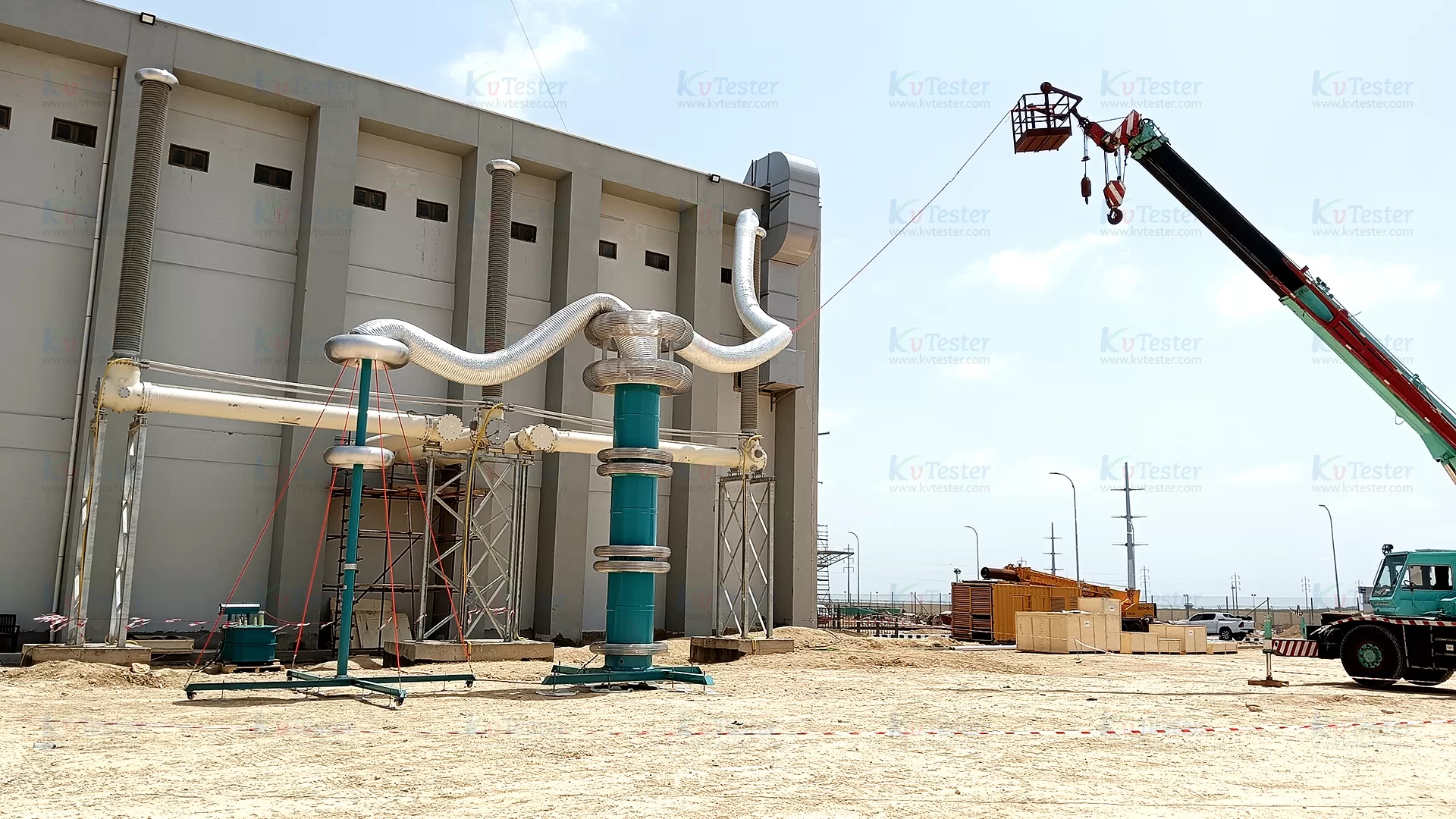
ZCVF-A series frequency conversion series resonant AC withstand voltage device is suitable for AC withstand voltage test of transformer, circuit breaker, switch, GIS system, cable, bushing, insulator and other equipment. It has the functions of high voltage over-voltage protection, low voltage over-current protection, detuning protection, zero position protection, flashover protection, emergency shutdown, under-voltage protection and so on. It not only meets the requirements of equipment test conditions for high voltage and small current, but also meets the requirements of equipment test conditions for low voltage and large current, and has a wide application range.
Kvtester Electronics Technology Co.,Ltd. is a high-tech enterprise specializing in power testing, testing, research and development, production, and sales of testing equipment. It has been engaged in the electrical testing industry for many years, and its products are of high quality. We welcome customers to come and purchase. Service hotline: 0086-27-81778799, to learn more, visit the official website: www.kvtester.com
Related Products





Latest News
-
 2026-09-18Why does the required capacity of series resonant test equipment usually increase with cable length?
 -
 2026-09-18How should 35kV cable series resonant withstand voltage test equipment be configured?
 -
 2026-09-18How to Select AC Withstand Voltage Test Equipment for 10kV Cables?
 -
 2026-09-18What parameters must be provided to the manufacturer when purchasing series resonant withstand voltage test equipment?
 -
 2026-09-18Multi-function Transformer Testing Equipment OEM Guide
