Home » News » Company News
PT Tester User Manual for Setup, Wiring and Testing
Using a PT tester correctly requires more than connecting the instrument and starting a measurement. Operators need to identify the voltage transformer terminals, select the appropriate test function, configure the required parameters, and verify the wiring before testing.
This guide explains the general operating procedures for common PT tests, including ratio and polarity testing, excitation characteristic testing, and secondary winding resistance measurement. It also covers result evaluation, data management, and common troubleshooting methods.
Please note that the user interface, connection terminals, and operating procedures may vary between PT tester models. This guide explains general operating principles and common testing procedures. Always refer to the user manual supplied with your specific instrument for exact wiring diagrams, parameter settings, and safety instructions.
What Should You Prepare Before Using a PT Tester?
Proper preparation helps prevent incorrect measurements and unnecessary interruptions.
Check the PT Tester and Accessories
Before operation, confirm that the instrument is suitable for your intended tests. Inspect the housing, display, terminals, power cable, and test leads for visible damage. Make sure all required accessories are available and that the power supply meets the instrument’s specifications.
Also check the available storage space if you need to save multiple test records.
Check the Voltage Transformer Information
Prepare the PT nameplate information before configuring the tester:
- Rated primary and secondary voltage
- Rated frequency
- Transformer type and winding configuration
- Terminal markings
- Accuracy class, where applicable
- Required test items
These details are important when entering test parameters and evaluating measurement results.
Prepare a Safe Testing Environment
Before connecting the instrument:
- Isolate the voltage transformer from the power system according to the approved work procedure.
- Verify the absence of voltage.
- Discharge and ground the relevant parts as required.
- Disconnect external circuits that may affect the measurement.
- Confirm that the testing area is safe and controlled.
Follow the applicable electrical safety rules and the grounding requirements in the tester manual.
How to Connect a PT Tester to a Voltage Transformer
Different test functions may require different wiring arrangements. Always select the correct connection diagram before attaching the test leads.
PT Ratio and Polarity Test Connection
A ratio and polarity test checks the transformation ratio and the relationship between primary and secondary terminal polarity.
Follow these general steps:
- Identify the primary and secondary terminals using the PT markings.
- Confirm that the transformer is isolated and safe to test.
- Select the ratio or polarity test function.
- Connect the test leads to the designated terminals according to the instrument’s wiring diagram.
- Check the lead connections and polarity markings.
- Verify the wiring before starting the measurement.
PT Excitation Test Connection
An excitation test evaluates the relationship between applied voltage and excitation current in an electromagnetic PT.
- Identify the winding specified for excitation testing.
- Isolate the PT from external circuits as required.
- Check the excitation test wiring diagram.
- Connect the excitation output and measurement leads to the designated terminals.
- Confirm the required grounding arrangement.
- Check all connections before enabling the test output.
The exact connection arrangement depends on the PT structure and tester model.
PT Secondary Winding Resistance Test Connection
This test measures the resistance of a selected secondary winding.
- Identify the secondary winding to be tested.
- Disconnect the relevant external circuits.
- Connect the resistance test leads to the specified terminals.
- Check that the connections are secure.
- Select the winding resistance function and verify the setup.
For DC resistance measurement, allow the instrument to complete the test and obtain a stable reading before recording the result.
How to Configure the PT Tester Before Testing
Although interfaces differ between models, most PT testers follow a similar setup process.
- Switch on the instrument and wait for the main interface.
- Select the required PT testing function.
- Choose the test item, such as ratio, polarity, excitation, or winding resistance.
- Enter the rated voltage and frequency information where required.
- Set other parameters according to the selected test.
- Confirm that the selected function matches the actual wiring.
- Review all settings before starting the measurement.
Some instruments provide wiring diagrams or connection guidance after a test function is selected. However, menu names and parameter requirements are not universal. Always follow the instructions for your specific model.
How to Perform Different PT Tests
Each test provides different information about the voltage transformer. Select the appropriate function according to the inspection or maintenance objective.
PT Ratio and Polarity Test
The ratio test determines the actual transformation ratio, while the polarity test checks the relationship between corresponding primary and secondary terminals.
- Select the ratio or polarity test function.
- Enter the rated primary and secondary voltage.
- Confirm the test lead connections.
- Check the selected winding and test configuration.
- Start the measurement and wait for completion.
- Review the measured ratio, ratio error, and polarity result where supported.
- Save the test record.
If the measured ratio differs from the expected value, check the input parameters, terminal identification, and wiring before repeating the test.
PT Excitation Characteristic Test
The excitation test evaluates the magnetic behavior of an electromagnetic PT by measuring the relationship between excitation voltage and current.
- Select the PT excitation test function.
- Confirm that the selected winding is suitable for the test.
- Check the required isolation and grounding arrangements.
- Verify the test lead connections and output limits.
- Start the test and allow the instrument to complete the measurement.
- Review the excitation curve and available characteristic values.
- Save the results for further analysis.
It is important to distinguish electromagnetic PT excitation testing from CVT testing. A capacitive voltage transformer has a different structure, so its testing requirements are not identical. A tester intended for CVT error measurement must explicitly support that function.
PT Secondary Winding Resistance Test
Secondary winding resistance testing checks the electrical resistance of the selected winding.
- Select the winding resistance function.
- Confirm that the winding is isolated from external circuits.
- Check the resistance test lead connections.
- Start the measurement and wait for a stable reading.
- Record the resistance and temperature if required.
- Repeat for other secondary windings when necessary.
- Save the measurement data.
Temperature can affect winding resistance. Consider this when comparing measurements taken at different times.
PT Ratio Error and Phase Angle Error Test
For metering and protection applications, ratio error and phase angle error are important indicators of voltage transformer measurement performance.
If the tester supports this function:
- Select the PT error measurement function.
- Enter the required rated voltage and winding information.
- Confirm the specified test conditions.
- Check the wiring against the instrument diagram.
- Start the measurement.
- Review the ratio error and phase angle error.
- Compare the results with the applicable accuracy class.
- Save the test record.
The available functions and measurement sequence depend on the tester model.
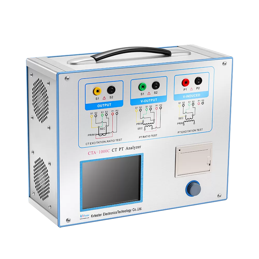
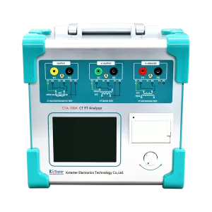
For example, the CTA-1000E supports PT ratio, polarity, secondary winding resistance, electromagnetic PT excitation characteristics, and ratio error testing. For dedicated electromagnetic PT and CVT error measurement, the PTA-2000C voltage transformer analyzer supports both types within its specified voltage range.
How to Read and Save PT Test Results
Completing a measurement is only part of the process. Operators should also check the results and maintain complete test records.
Review and Evaluate the Results
Depending on the selected function, the tester may display:
- Transformation ratio and ratio error
- Phase angle error
- Polarity
- Excitation voltage-current curve
- Secondary winding resistance
Check that each result corresponds to the correct PT, winding, and test item. Compare the measurements with the nameplate, applicable standards, accuracy class, and historical records.
If a result appears abnormal, first verify the input parameters, wiring, terminal selection, and test conditions. Repeat the measurement if the setup may have affected the result rather than immediately concluding that the transformer has an internal fault.
Save and Export Test Data
A typical data management process includes:
- Confirm that the measurement is complete.
- Enter the PT identification information if supported.
- Save the test record.
- Check that the record appears in the stored data list.
- Connect a compatible USB drive or computer if external export is required.
- Export the selected records according to the instrument instructions.
- Verify that the exported files are readable.
For example, the CTA-1000E provides internal storage for up to 10,000 groups of test data and supports USB data export, helping testing teams organize and review measurement records.
Common PT Tester Problems and How to Solve Them
The Tester Cannot Start the Measurement
Possible causes include incorrect test mode selection, incomplete parameters, loose connections, or an instrument protection warning.
Check the selected function, required input parameters, test leads, and any error messages displayed by the instrument. If the problem remains, follow the model-specific troubleshooting instructions.
The Test Result Is Unstable
Unstable readings may be caused by loose test leads, poor terminal contact, electrical interference, or unsuitable test conditions.
Stop the measurement and follow the required safety procedure before checking the connections. Inspect the leads, confirm firm terminal contact, and review the grounding and isolation arrangements before testing again.
The Measured Ratio Does Not Match the Rated Ratio
First check whether the rated primary and secondary voltage values were entered correctly. Then verify the terminal markings, winding selection, and connection diagram. Multiple secondary windings or special PT configurations may require particular attention.
Test Data Cannot Be Saved or Exported
Check the available storage space and confirm that the measurement has finished. If using a USB drive, verify its compatibility with the tester and follow the instrument’s export procedure. Always check that the exported file is readable before removing the storage device.
Choosing a PT Tester with Easy Operation and Data Management
When selecting a PT tester, consider its supported test functions, measurement range, connection guidance, and data management capabilities.
A clear interface and built-in wiring guidance can help technicians reduce setup errors. Automatic measurement and result analysis can improve testing efficiency, while internal storage and USB export make it easier to maintain records.
You should also confirm that the instrument supports the voltage transformer types used in your application. For teams handling both CT and PT testing, the CTA-1000E provides multiple testing functions in one instrument. For applications requiring dedicated PT and CVT error measurement, the PTA-2000C offers corresponding testing capabilities.
Conclusion
Operating a PT tester correctly involves preparing the instrument and transformer information, confirming the wiring, configuring test parameters, performing the required measurements, and reviewing and saving the results.
Because connection methods and operating interfaces vary between models, always follow the wiring diagrams and safety instructions supplied with your instrument. If you need help selecting a suitable PT tester or confirming its testing capabilities, contact Kvtester for technical support and equipment recommendations.
Related Products
Latest News
-
 2026-11-12CT PT Analyzer Excitation Testing for CT and PT Evaluation
-
 2026-11-12CVT PT Tester for Accurate Voltage Transformer Testing
-
 2026-11-12Testing Large Power Transformers with a Short Circuit Impedance Tester
-
 2026-11-11Digital CT PT Analyzer for Smarter Transformer Testing
-
 2026-11-11CT PT Analyzer Polarity Test for Accurate CT and PT Verification