Home » News » Company News
Transformer Tester for Substation Testing and Selection
A transformer tester for substation applications helps verify equipment condition, identify winding faults, and assess electrical performance before energization and during routine maintenance. Choosing the right tester depends on the transformer type, the measurements required, and the testing conditions. Understanding these factors makes it easier to select suitable equipment, interpret results accurately, and reduce the risk of unexpected failures.
Why Transformer Testing Matters in Substations
Power transformers operate under changing loads and electrical conditions. During transportation, installation, commissioning, and long-term service, their windings, connections, insulation, and other components may develop defects that affect reliability.
Transformer testing provides measurable information about equipment condition. Before a transformer is energized, test results can help confirm that installation and electrical characteristics meet the relevant requirements. During maintenance, comparisons with previous measurements can reveal changes that may require further investigation.
A suitable testing plan should consider several objectives:
- Verify winding resistance and identify possible connection problems.
- Measure no-load and load characteristics to assess electrical performance.
- Check transformer capacity and related operating parameters where required.
- Establish baseline measurements for future maintenance comparisons.
- Record results consistently for troubleshooting and maintenance planning.
Not every transformer requires every test during each maintenance visit. The appropriate scope depends on the transformer design, operating history, applicable standards, and the purpose of the inspection. Our guide to transformer testing equipment for grid maintenance provides further context for planning tests around maintenance requirements.
Key Measurements to Check With a Transformer Tester
A transformer tester is not necessarily a single instrument that performs every diagnostic task. Different measurements require different test functions, connection arrangements, and operating procedures.
Winding DC resistance
Winding DC resistance testing measures the resistance of transformer windings. It can help identify loose connections, poor contact, winding defects, and differences between phases.
For three-phase transformers, technicians should compare phase measurements under consistent conditions. Winding temperature also matters because conductor resistance changes with temperature. When comparing results from different dates, temperature correction and the manufacturer’s acceptance criteria should be considered.
The test should be performed with the transformer isolated and properly prepared. Because transformer windings are inductive, technicians must also follow the instrument’s discharge procedure before disconnecting test leads.
No-load current and no-load loss
No-load testing evaluates the transformer’s behavior when its secondary winding is open and the prescribed test voltage is applied to the appropriate winding. The measured no-load current and loss provide information about magnetic performance and can help identify abnormal results.
Test voltage, frequency, waveform quality, and connection configuration influence the measurements. Results should therefore be evaluated against the transformer’s rated data, applicable test procedures, and previous records rather than judged in isolation.
Load loss and impedance voltage
Load testing assesses losses and impedance characteristics under the specified test conditions. Load loss is associated mainly with winding resistance and other load-dependent effects, while impedance voltage reflects the voltage required to produce the specified current under short-circuit test conditions.
These measurements are useful for checking transformer performance and comparing test results with technical requirements. Accurate connections, correct instrument ranges, and suitable test conditions are essential for reliable readings.
Transformation ratio and winding connections
The transformation ratio helps verify the relationship between primary and secondary winding voltages. Checking the winding connection group and polarity, where applicable, helps confirm that the transformer is configured correctly.
These checks are particularly important after installation, repair, or winding-related work. The test method should match the transformer configuration and the instrument’s supported functions.
How to Match a Transformer Tester to the Required Task
Before choosing equipment, identify the measurements needed for commissioning or maintenance. Selecting instruments according to actual test requirements is more effective than choosing a device simply because it offers a large number of functions.
For winding resistance measurements
A dedicated DC resistance tester is appropriate when the main objective is to measure winding resistance and compare phase values.
Our ZC-205A DC Resistance Tester provides selectable output currents of 10 A, 5 A, 1 A, 200 mA, 20 mA, and 2 mA. Its measurement ranges vary by selected current, from 0–250 mΩ at 10 A to 100 Ω–30 kΩ at 2 mA. The instrument has a minimum resolution of 0.1 μΩ and an accuracy specification of ±(0.2% of reading + 2 words).
The ZC-205A also supports three-phase winding data display and printing, unbalance-rate calculation, and resistance conversion to a rated temperature. These functions help technicians organize measurement results and compare winding resistance under defined conditions.
For transformer capacity and load-related tests
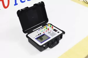
When testing requires capacity identification and measurements such as no-load current, no-load loss, load loss, and impedance voltage, a transformer capacity and load tester may be more suitable.
The ZC-202B Transformer Capacity and Load Tester supports these measurement tasks, along with three-phase no-load and load testing functions. It can also display voltage and current vectors and apply waveform, temperature, non-rated-voltage, and non-rated-current corrections.
Its capacity test ranges depend on transformer type and rated voltage. For example, the specified ranges include 30–3,150 kVA for 10 kV dry-type and oil-immersed transformers, while the range for 35 kV oil-immersed transformers is 50–31,500 kVA. These ranges should be checked against the actual transformer and intended test method before selecting the instrument.
For multiple transformer test functions
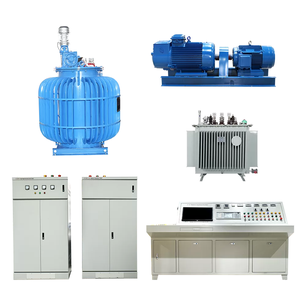
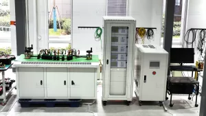
Some substation testing arrangements require a coordinated system rather than a standalone portable tester. In these cases, a transformer test control desk can help organize several test functions and support a more consistent workflow.
Our ZC-200 Transformer Test Control Desk is designed for tests including no-load characteristics, load characteristics, winding resistance, transformation ratio and group, power-frequency withstand voltage, induction withstand voltage, and insulation resistance of power and distribution transformers.
The system uses a PLC and industrial control computer. Its test units can operate independently or under computer control, with data acquisition and report generation supporting the testing process. Its specified voltage measurement range is 0.1–650 V, and its current measurement range is 0.1–300 A. These are measurement ranges for the control desk, not a statement of the voltage rating of every transformer it can test. The required external test equipment and configuration must also be considered.
What to Consider Before Selecting a Substation Transformer Tester
Several practical factors affect whether a tester is suitable for a particular substation.
- Transformer specifications: Confirm rated voltage, capacity, winding configuration, connection group, and transformer type. Equipment ranges must match the intended test conditions.
- Required test functions: List the measurements needed for commissioning, acceptance, troubleshooting, or periodic maintenance. A resistance tester may be sufficient for one task, while a coordinated test system may be needed for broader testing.
- Accuracy and resolution: Check both specifications and the measurement range in which they apply. High resolution alone does not guarantee that a measurement is accurate enough for the intended purpose.
- Data management: Storage, printing, computer transfer, and report generation can make it easier to maintain consistent records and compare results over time.
- Field conditions: Consider available power supplies, ambient temperature, transport requirements, cable arrangements, and the working space around the transformer.
- Safety features: Review overcurrent protection, interlocks, discharge indications, grounding requirements, and operating procedures. Protective functions do not replace isolation, grounding, and other site safety measures.
It is also important to distinguish between the instrument’s measurement range and the maximum transformer rating supported by a complete test arrangement. Some tests require external power sources, voltage regulators, loading equipment, or other accessories. Confirm the complete configuration before purchasing equipment for a specific transformer.
Transformer Testing During Commissioning and Maintenance
The purpose of testing influences both the selection of equipment and the interpretation of results.
During commissioning, technicians generally verify that the transformer is correctly installed and that the required electrical characteristics meet the applicable specifications. Depending on the project, this may include winding resistance, transformation ratio, winding connection checks, insulation-related tests, and no-load or load characteristics.
During routine maintenance, the emphasis is often on detecting changes. Historical test results are particularly valuable because an isolated reading may not reveal a developing problem. A change in winding resistance, for example, should be reviewed alongside temperature, test connections, phase differences, and earlier measurements before drawing a conclusion.
When abnormal results appear, repeat the measurement under controlled conditions and verify the test setup. Check that connections are secure, the correct test method is being used, and relevant temperature or other corrections have been applied. If the result remains outside the expected range, further investigation should follow the manufacturer’s guidance and applicable standards.
Testing records should include the transformer identification, test date, environmental or winding temperature where relevant, instrument details, connection method, measured values, and any corrections applied. Consistent records make future comparisons more meaningful and help maintenance teams prioritize follow-up inspections.
Building a Practical Transformer Testing Plan
A useful testing plan begins with the purpose of the work rather than a particular instrument model. For each transformer, identify the required tests, applicable acceptance criteria, safety arrangements, and the equipment needed to perform each measurement.
For example, a team checking winding condition may prioritize DC resistance testing, while a team verifying transformer capacity and loss characteristics may require a capacity and load tester. A facility performing several types of electrical tests may benefit from a coordinated test system that supports data collection and reporting.
Before testing begins, confirm that the transformer is in the required electrical state, the test connections are correct, and the equipment has suitable ranges and accessories. After testing, review the results against technical requirements and previous records, then document any deviations and necessary follow-up actions.
This approach keeps the testing process focused, avoids unnecessary equipment purchases, and helps ensure that the selected transformer tester meets the real requirements of substation work.
Conclusion
Choosing a transformer tester for substation applications requires a clear understanding of the measurements needed, the transformer’s specifications, and the conditions under which testing will take place. Winding resistance testers, capacity and load testers, and coordinated transformer test control systems serve different purposes, so their functions and measurement ranges should be checked against the intended work.
By matching equipment to specific testing tasks, following appropriate safety procedures, and maintaining consistent test records, substation teams can make better-informed decisions during commissioning, troubleshooting, and routine maintenance.
Related Products
Latest News
-
 2026-10-23Substation CT Tester: How to Choose the Right CT Tester for Commissioning
-
 2026-10-20CVT Compatible CT PT Analyzer: Selection Guide
-
 2026-10-20China CT PT Analyzer Supplier: Manufacturer Guide
-
 2026-10-20CT PT Test System: Testing Methods and Equipment Selection
-
 2026-10-16How can measurement errors in no-load tests be minimized?