
Home » News » Company News
Transformer Testing Equipment for Grid Maintenance Guide
Transformer maintenance decisions improve when results can be compared across the asset lifecycle. A resistance value, no-load loss result, or impedance measurement becomes more informative when the team can relate it to a factory record, commissioning baseline, earlier outage, tap position, test temperature, repair history, and operating condition.
Grid maintenance programs therefore need both suitable test equipment and a disciplined approach to recordkeeping. The objective is to build evidence that supports repair, return-to-service, monitoring, or escalation decisions.
Establish a Maintenance Baseline
A utility should establish a structured baseline when a transformer is delivered, commissioned, repaired, or first brought into a planned maintenance program. That baseline should include the transformer nameplate, winding arrangement, tap position, cooling condition, reference temperature, test method, and results relevant to the asset type.
- Winding DC resistance
- Transformation ratio and vector group
- No-load current and no-load loss
- Load loss and impedance voltage
- Insulation resistance
- Power-frequency withstand voltage where required
- Induced withstand voltage where required
- Visual inspection and connection condition
- Earlier repair findings and component replacements
The same identification fields should be retained during later tests. A result without a clear transformer reference, tap setting, temperature, and test method is difficult to compare reliably.
Use Winding Resistance for Trend Review
DC winding resistance is one of the most practical tests for utility maintenance. It can support phase comparison, connection inspection, post-repair verification, tap-related checks, and review of temperature-corrected values.
The ZC-205A DC Resistance Tester offers output-current selections from 2 mA to 10 A, 0.1 μΩ resolution, and stated measuring accuracy of ±(0.2% of reading + 2 words). It can display and print three-phase winding data, calculate three-phase unbalance, and show resistance values converted to a selected reference temperature.
The team should record the winding or phase, tap position, test current, measured resistance, temperature, reference-temperature result, connection method, and test date. A phase imbalance or difference from earlier data should trigger a review of the context before an asset conclusion is made.
After a resistance test, keep leads connected until the discharge process has finished. ZC-205A includes an audible and visual discharge indication, along with wiring inspection and overcurrent protection.
Use Loss and Impedance Results in Context
No-load current and no-load loss provide information related to the transformer’s no-load operating behavior. Load loss and impedance-voltage results support review of load characteristics and impedance-related performance.
The ZC-202B Transformer Capacity and Load Tester measures transformer capacity, no-load current, no-load loss, short-circuit or load loss, and impedance voltage. It supports automatic range switching and corrections for waveform, temperature, non-rated voltage, and non-rated current conditions.
For grid maintenance, these values should be reviewed against the transformer rating, prior comparable tests, applicable project procedures, and known repair history. A changed result can indicate the need for further engineering review, but it should not be treated as an isolated pass/fail decision without considering test conditions.
Set Up a Maintenance Workflow
The equipment configuration should reflect the maintenance location and workload.
Field teams often need portable, task-specific instruments for winding resistance, ratio verification, insulation checks, or no-load/load testing. Regional workshops and transformer repair centers may need a controlled environment for repeatable multi-item tests, including high-voltage procedures.
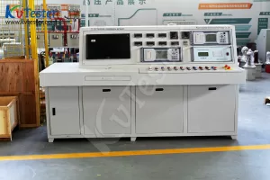
The ZC-200 Transformer Test Control Desk is intended for transformer production and maintenance departments. Its test scope includes no-load and load characteristics, power-frequency withstand voltage, induced withstand voltage, and temperature-rise testing. The system is designed for stated three-phase transformer testing up to 3150 kVA/10 kV and uses controlled measurement and test functions to support a structured workflow.
A centralized test platform can help a utility or repair center standardize data collection, test sequencing, controlled voltage changes, and safety responsibilities. Site-specific design, transformer ratings, local electrical supply, and approved safety arrangements should be confirmed before specifying a system.
Retain Data That Can Be Compared
Maintenance records should help engineers answer practical questions over time:
- Has the winding resistance changed compared with the last comparable test?
- Are phase values balanced within the expected context?
- Was the same tap position used?
- Was the temperature correction applied consistently?
- Are no-load and load results aligned with the maintenance baseline?
- Did the transformer undergo repair, transport, relocation, or tap-changer work?
- Is the asset ready for a further test stage or return to service?
The ZC-205A stores up to 1,000 groups of test data. ZC-202B stores up to 500 groups and supports computer data transfer. These capabilities can support a disciplined maintenance record process when the organization uses consistent asset naming and test documentation.
Support Return-to-Service Decisions
Transformer testing equipment is most valuable when it helps teams make better maintenance decisions. Portable instruments can support repeatable field measurements. A comprehensive test system can support controlled workshop testing after repair or before delivery. Both approaches require qualified personnel, approved isolation and grounding procedures, and records that preserve the test context.
A maintenance program should connect test results to asset history rather than storing them as isolated readings. That approach strengthens planning, fault investigation, repair verification, and return-to-service review.
Related Products





Latest News
-
 2026-09-21Smart Transformer Testing Equipment: Features for Efficient Testing
 -
 2026-09-20CT PT Analyzer for Commissioning: Substation Testing Guide
 -
 2026-09-20ANSI Standard CT Tester: Specs, Tests & Buying Guide
 -
 2026-09-18Why does the required capacity of series resonant test equipment usually increase with cable length?
 -
 2026-09-18How should 35kV cable series resonant withstand voltage test equipment be configured?
