
How can measurement errors in no-load tests be minimized?
How can measurement errors in no-load tests be minimized?
Transformer no-load tests are primarily conducted to measure no-load loss and no-load current. Due to the low magnitude of no-load current and the low power factor, test results are susceptible to factors such as power supply quality, instrument accuracy, wiring configuration, and core remanence. Therefore, obtaining reliable no-load test data requires controlling errors related to the test power supply, measuring instruments, and operational procedures.
1. Ensure stable test voltage and frequency
No-load loss is closely linked to the applied voltage; deviations in test voltage result in changes to the measured no-load loss. Consequently, the test must be conducted by applying the rated frequency and specified voltage, with data recorded only after the voltage has stabilized. For three-phase transformers, it is also essential to ensure the balance of the three-phase test voltages to prevent excessive voltage imbalances from skewing the measurements of no-load current and loss. GB/T 1094.1-2013 stipulates that no-load loss and no-load current measurements must be performed at the rated frequency and the corresponding specified voltage.
2. Pay attention to the waveform quality of the test power supply
Voltage waveform distortion is a source of error often overlooked during no-load testing. When a transformer operates at no-load, the excitation current inherently contains significant harmonic content; if the test power supply has insufficient capacity or high impedance, further voltage waveform distortion may occur, thereby affecting no-load loss measurements.
In accordance with the measurement methods specified in GB/T 1094.1-2013, both the average voltage value and the root-mean-square (RMS) voltage value must be monitored. A significant discrepancy between these two readings indicates that the test voltage waveform quality may not meet requirements; the standard stipulates that the difference between the two readings must not exceed 3% for the waveform to be considered compliant. Therefore, the test power supply used for no-load testing should ideally have sufficient capacity, stable output, and good waveform quality.
3. Select testing instruments with appropriate accuracy and measurement ranges
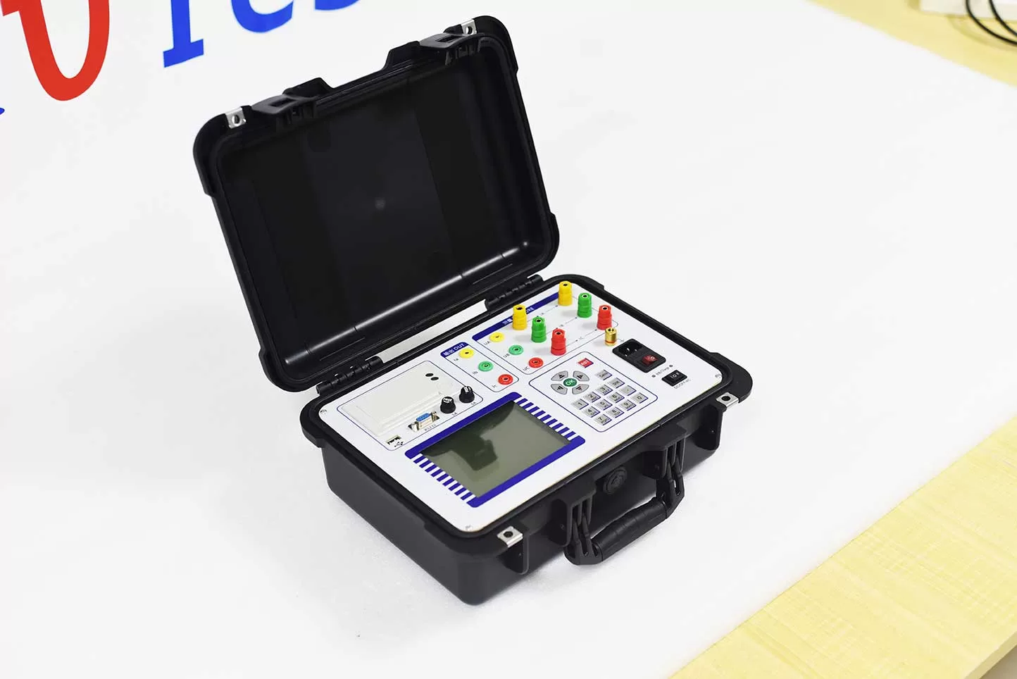
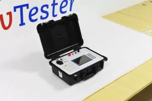
No-load tests typically involve low power factors, making power measurements highly sensitive to the phase error of the instruments. For testing, select a transformer comprehensive tester, electrical parameter tester, or power measuring device with an accuracy that meets the test requirements, and choose an appropriate measurement range based on the actual voltage and current levels.
Selecting a range that is too large may reduce the effective measurement resolution, while a range that is too small may lead to an “out-of-range” condition. Furthermore, test instruments must be verified or calibrated in accordance with relevant regulations to minimize inherent instrument error.
4. Check test connections and contact status
Loose test leads, poor terminal contact, or incorrect wiring can all lead to anomalous measurement results. Before testing, verify the voltage, current, and power measurement circuits, and ensure that all terminals are securely connected. When using voltage or current transformers to extend the measurement range, pay close attention to the transformation ratio, polarity, and potential measurement errors. For three-phase no-load tests, ensure that the wiring configuration is consistent across all phases, and record the voltage, current, and power data for each phase simultaneously once the voltage has stabilized.
5. Consider the impact of core remanence
If a transformer has recently undergone a DC resistance test, residual magnetism (remanence) may be present in the core. This remanence alters the initial magnetization state of the core, which in turn affects the no-load current and no-load loss. The standard GB/T 1094.1-2013 explicitly states that if a no-load test is conducted following a resistance measurement—or any other test that might cause pre-magnetization of the core—the effects of remanence must be considered and addressed. Therefore, for no-load loss tests requiring high precision, the transformer should be demagnetized using an appropriate method before proceeding with the actual measurements.
6. Perform repeat measurements and data verification
After completing a no-load test, do not rely solely on a single set of data for evaluation. If the no-load loss or no-load current appears significantly high, or if the three-phase data show irregularities, repeat the test under identical conditions while verifying the power supply voltage, frequency, waveform, and wiring. Additionally, compare the test results against the transformer’s nameplate specifications, factory test data, and historical test records. If repeated test results are stable but still exhibit a significant deviation, further analysis should be conducted regarding factors such as the transformer core, clamping components, and the unit’s manufacturing or operational status.
Conclusion
To reduce measurement errors during transformer no-load tests, it is essential to ensure the accuracy of the test voltage and frequency, control voltage waveform distortion, select appropriate measuring instruments, and properly manage test connections and core remanence. By standardizing test conditions, cross-verifying test data, and comparing results against factory specifications and historical data, the accuracy and reliability of no-load loss and no-load current measurements can be improved.
Related Products





Latest News
-
 2026-10-16Why is the no-load test on a transformer typically conducted by applying voltage to the low-voltage side?
 -
 2026-10-16What are the consequences of non-compliant short-circuit impedance?
 -
 2026-10-15What are the differences between insulation resistance, absorption ratio, and polarization index?
 - 2026-10-15What is the purpose of a transformer load test?
-
 2026-10-15What causes unstable results in transformer DC resistance tests?
