Features and Advantages
1. SF₆ gas insulation for convenient on-site use
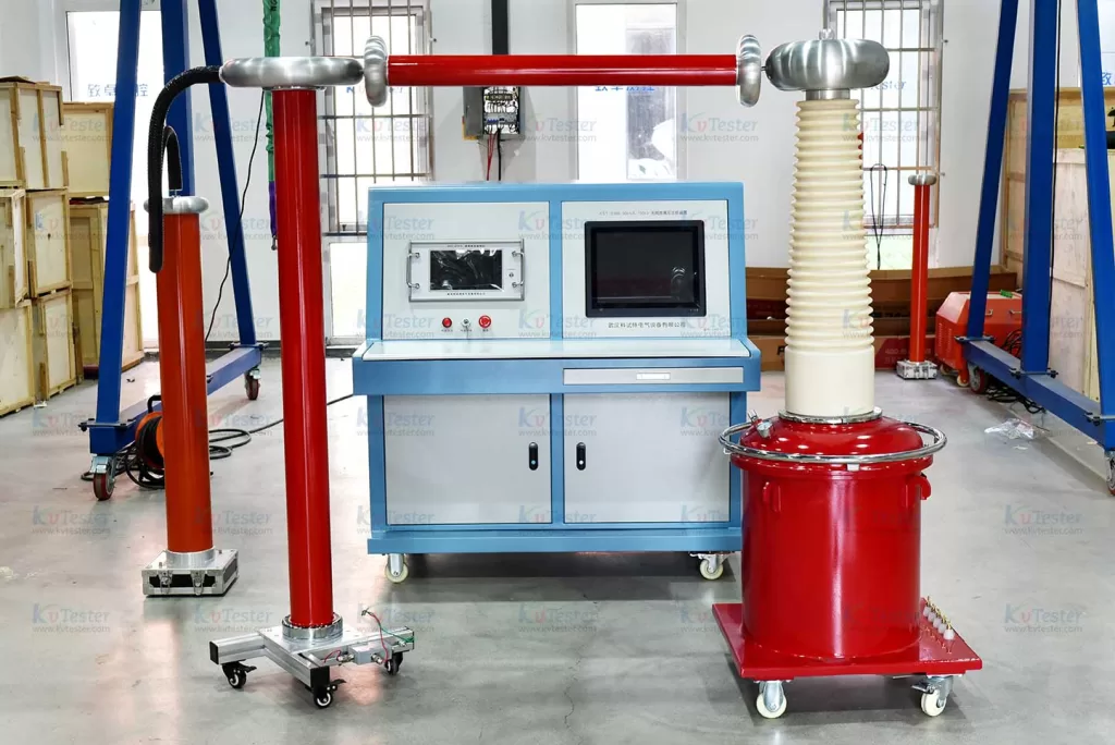
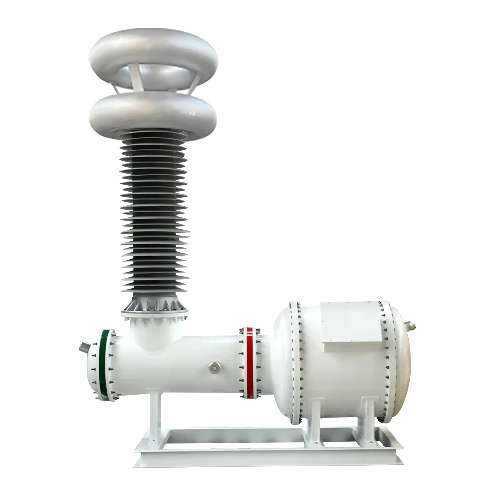
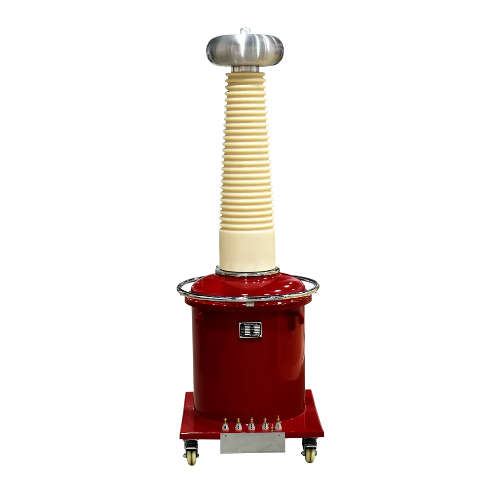
Utilizing a gas-insulated structure, the system is compact, lightweight, and free from oil contamination, making it ideal for on-site testing and work environments requiring frequent relocation.
2. Combination of low-PD structure and power isolation filtering
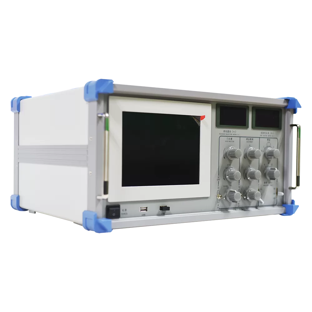
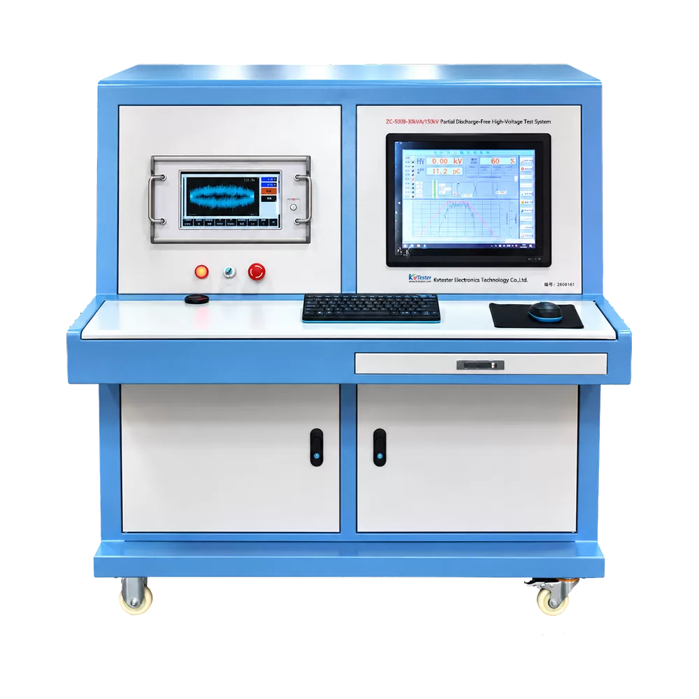
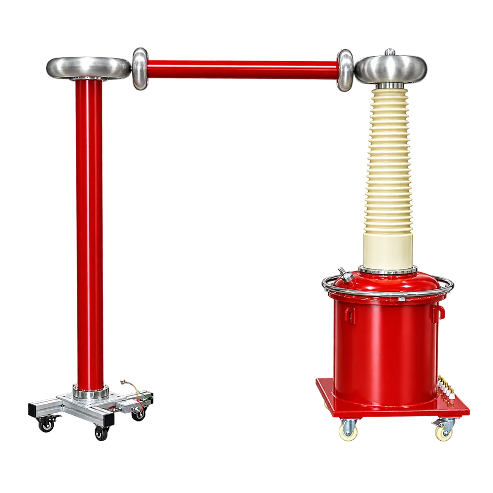
The partial discharge-free test transformer employs specialized electrical design and manufacturing techniques to minimize the impact of the transformer’s own partial discharge on test results; the control console features a built-in isolation filter to suppress power supply noise and interference.
3. Automatic and manual operation with multi-stage testing support
Supports both automatic programmed control and manual step-by-step operation. In automatic mode, users can configure 1 to 3 test stages, setting specific target voltages, voltage ramp rates, and withstand durations for each; the system automatically executes voltage ramping, timing, voltage reduction to zero, and circuit disconnection according to the preset sequence, while automatically saving test data. Two-stage and three-stage withstand tests are available only in automatic mode.
4. Digital touch-based detection with convenient parameter settings
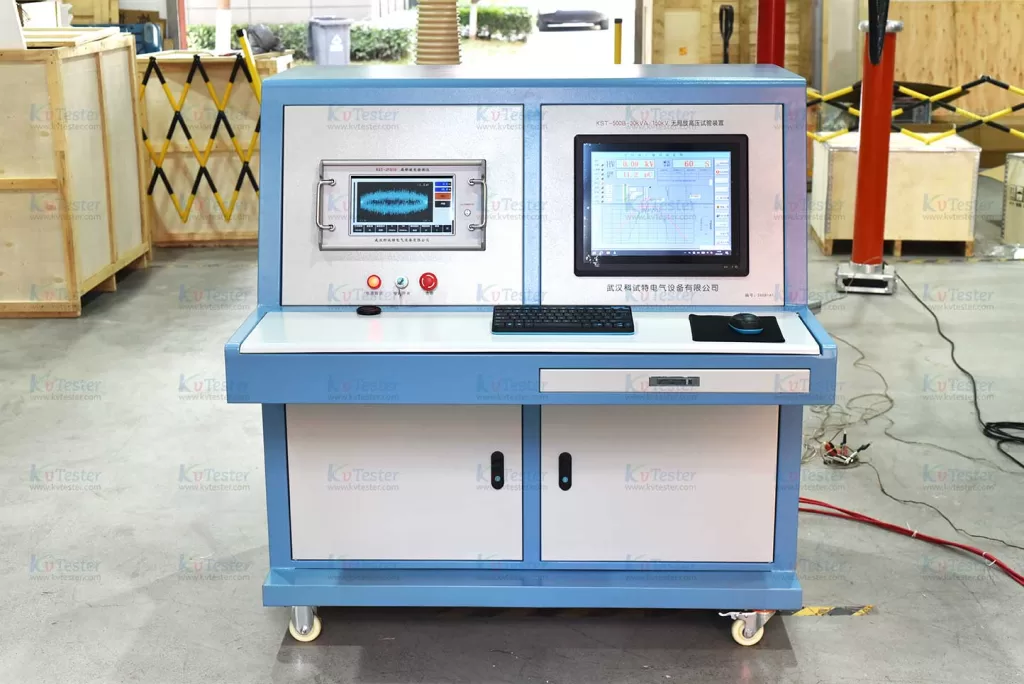
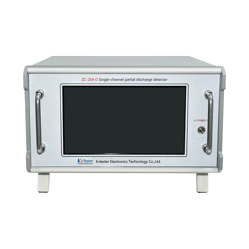
The partial discharge detector utilizes a high-performance 32-bit microcontroller and a 10.1-inch capacitive touchscreen, supporting one-touch automatic calibration, test voltage divider ratio configuration, and serial data upload. It offers nine frequency band combinations and a dual time-window function, allowing users to select frequency bands and adjust the position and width of time windows to avoid fixed-phase interference.
5. Real-time display of test parameters; support for data and report management
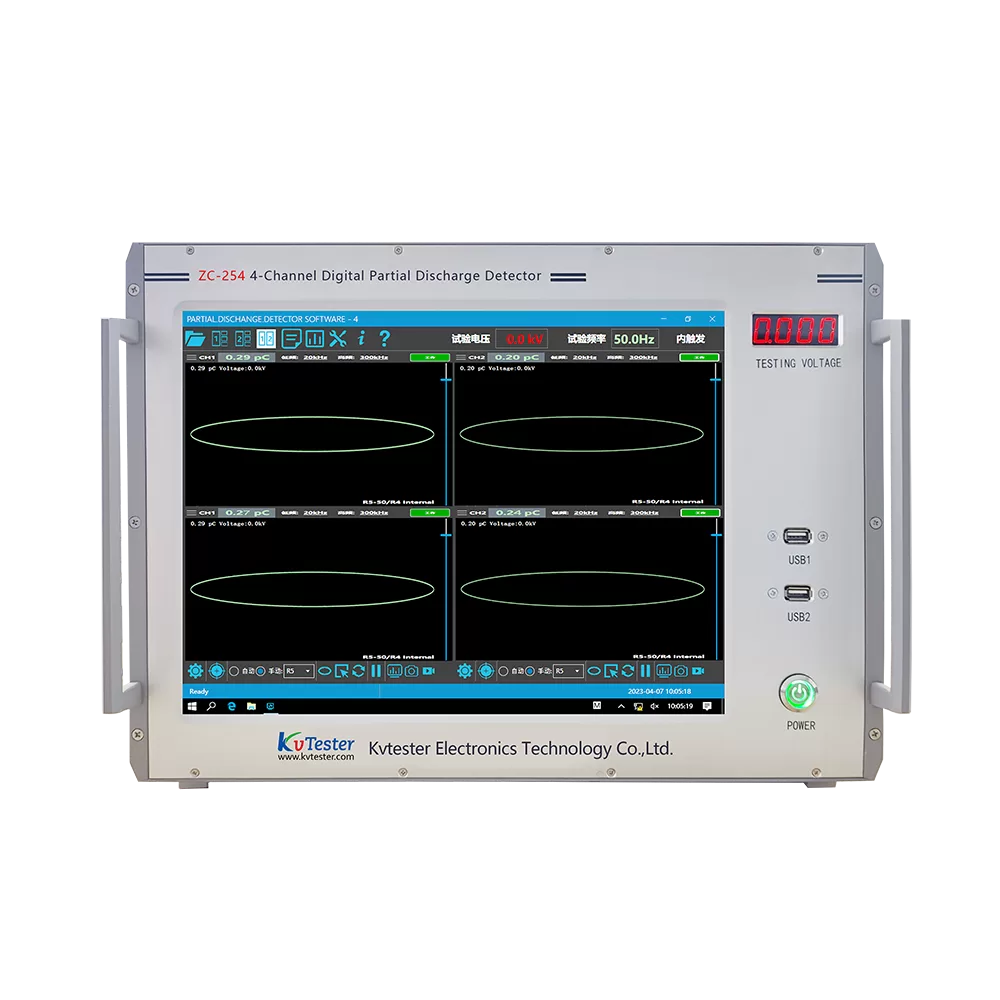
The control software displays high-voltage levels, withstand duration, partial discharge magnitude, and voltage-time curves in real time. Data is automatically saved and reports are generated upon test completion; the system supports the retrieval of historical test records, facilitating the organization and traceability of results.
6. Equipped with protection and emergency shutdown functions
The system allows for the configuration of protection parameters—such as overvoltage and overcurrent limits—and incorporates zero-start interlocking and emergency shutdown capabilities. Stop controls are available on both the software interface and the equipment panel, enabling voltage reduction and circuit disconnection in accordance with the operating manual.
Parameter
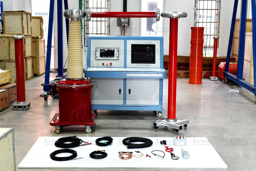
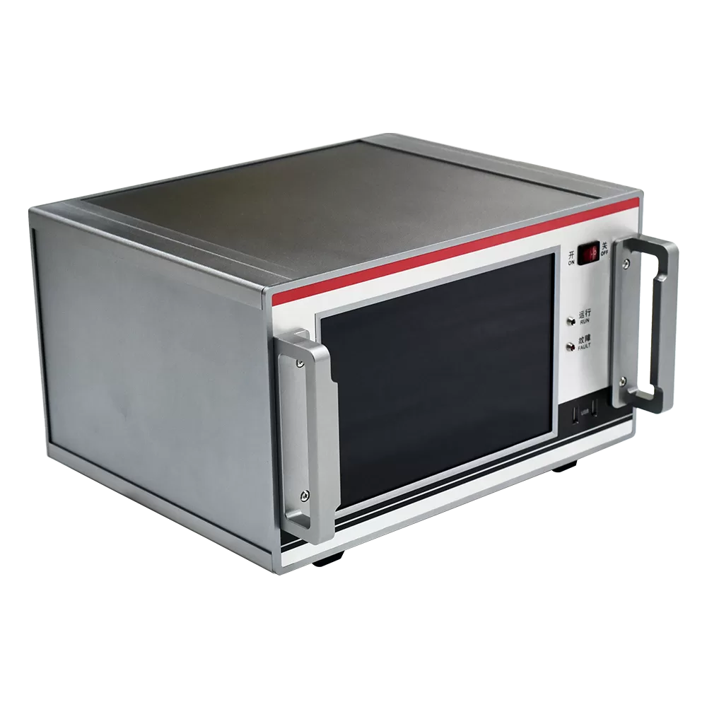
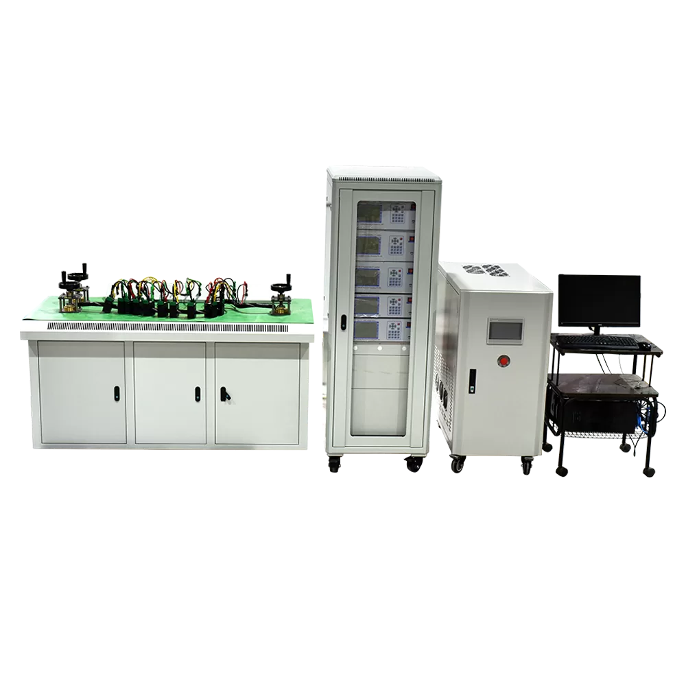
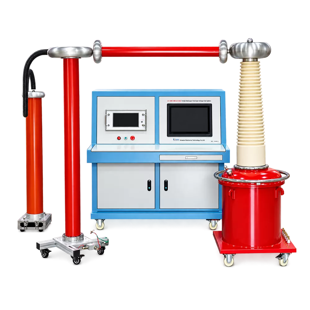
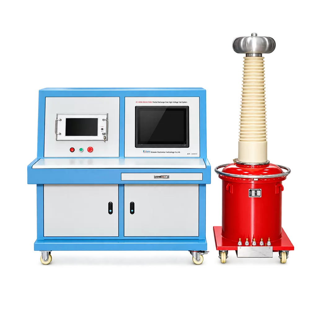
- Fully Automatic Control Console and Test Transformer
- Partial Discharge Detector
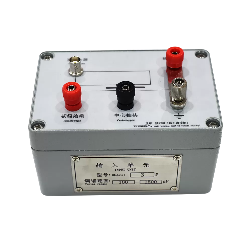
- Isolation Filter
- Partial Discharge-Free Coupling Capacitor
| Fully Automatic Control Console and Test Transformer | ||
| Parameter | Fully Automatic Control Console | Partial Discharge-Free Test Transformer |
| Rated Capacity | 30 kVA | 30 kVA |
| Input Voltage | 380 V AC ±10%, single-phase | 0–400 V AC, single-phase |
| Input Current | 75 A | 75 A |
| Output Voltage | 0–430 V, single-phase | 0–150 kV, single-phase |
| Output Current | 0–75 A | 0–200 mA |
| Voltage Measurement Accuracy | 0.5% | — |
| Current Measurement Accuracy | 0.5% | — |
| Metering Winding Voltage | — | 100 V, single-phase |
| Partial Discharge Detector | |
| Parameter | Specification |
| Detection Channels | Single channel |
| Display | 10.1-inch capacitive touchscreen |
| Test Object Capacitance Range | 6 pF–250 μF |
| Detection Sensitivity | 0.02–10 pC, depending on the input unit and tuning capacitance range; applicable to the unbalanced test circuit conditions specified in the manual |
| Amplifier Lower Cutoff Frequency (fL) | 10, 20, or 40 kHz, selectable |
| Amplifier Upper Cutoff Frequency (fH) | 80, 200, or 300 kHz, selectable |
| Frequency Band Combinations | 9 |
| Gain Adjustment | Coarse adjustment: 6 settings, with a gain difference of 20 ± 1 dB between adjacent settings; fine adjustment range: >20 dB |
| Elliptical Sweep Time-Base Frequency | 50/60, 100, 150, 200, 400 Hz |
| Sweep Display Modes | Elliptical, sinusoidal, and linear |
| Time Windows | Two time windows, which can be enabled individually or simultaneously |
| Time Window Width | Adjustable from 5° to 170° at 50 Hz |
| Time Window Position | Each window is adjustable from 0° to 170° |
| Pulse Peak Indication Error | ±3% of full scale |
| Test Voltage Display Range | 150 kV |
| Test Voltage Indication Error | ±1% |
| Voltage Measurement Input Impedance | >1 MΩ |
| Overall Dimensions | 370 × 460 × 215 mm |
| Weight | Approximately 12.5 kg |
| Isolation Filter | |
| Parameter | Specification |
| Input Voltage | 400 V ±10% |
| Output Voltage | 400 V ±10% |
| Rated Capacity | 30 kVA |
| No-Load Loss | ≤5% |
| Impedance Voltage | ≤5% |
| Attenuation | ≥20 dB over the 10–100 kHz frequency range |
| Overall Dimensions | 550 × 400 × 550 mm |
| Weight | 80 kg |
| Partial Discharge-Free Coupling Capacitor | |
| Parameter | Specification |
| Rated Voltage | 150 kV |
| Rated Capacitance | 400 pF |
| Dielectric Dissipation Factor (tan δ) | ≤0.2% |
| Insulation Level | Withstands 120% of rated voltage for 1 min with no abnormalities |
| Nominal Divider Ratio | 1000:1 |
| Partial Discharge Magnitude | ≤5 pC at 100% of rated voltage; test duration: 30 min |