Features and Advantages
1.Multi-Channel Synchronization
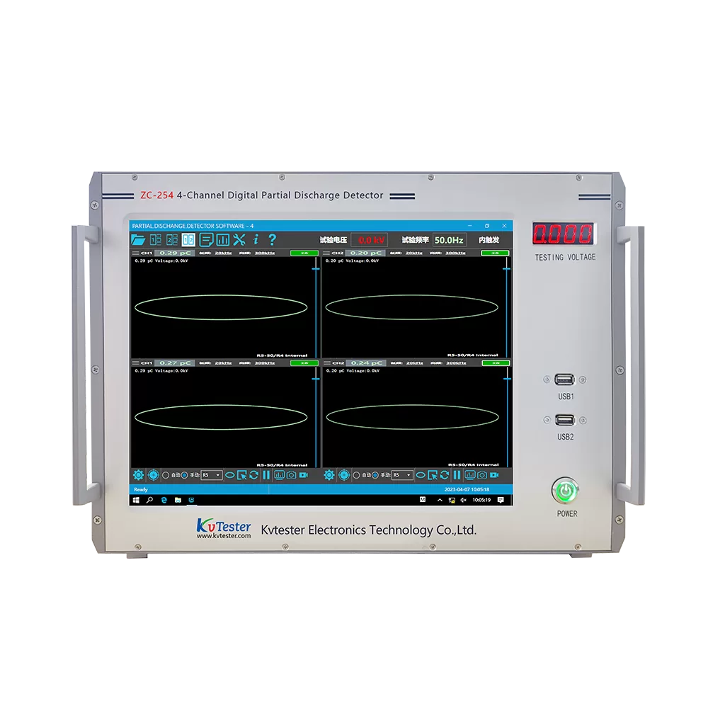
Features an independent four-channel design, enabling simultaneous signal sampling, processing, and display.
2.Dual-Mode Testing
Capable of performing partial discharge detection for both AC and DC power sources simultaneously.
3.Flexible Synchronization Triggering
Supports seamless switching between internal and external synchronization modes; the external trigger accommodates frequencies ranging from 50 Hz to 400 Hz and includes zero-crossing indication and phase-resolving capabilities.
4.Diverse Display Modes
Offers switchable display modes—Elliptical, Linear, and Sinusoidal—and supports the visualization of partial discharge patterns in both 2D and 3D formats.
5.Robust Anti-Interferenc
Employs a hybrid analog-digital filtering system with freely combinable frequency bands; features advanced anti-static interference and correlation filtering capabilities to effectively eliminate fixed-phase and non-synchronous random noise.
6.Precise Measurement Control
Each channel features independent coarse and fine gain adjustments; supports 360° arbitrary phase windowing, allowing for the selection of single, dual, or multiple phase windows
7.Intelligent Data Processing
Supports data storage and playback, waveform saving, test recording, and single-pulse capture analysis; automatically generates standard test reports with full printing support.
8.System Compatibility & Expandability
Can be integrated with MES and ERP systems to facilitate digital industrial management.
9.Comprehensive Monitoring
While detecting partial discharge, the device simultaneously monitors the test voltage in real-time, enabling a comprehensive analysis of discharge pulse waveforms, timing, and magnitude.
10. Convenient Calibration
Paired with a dedicated calibration pulse generator, it supports independent, automatic calibration for each individual channel.
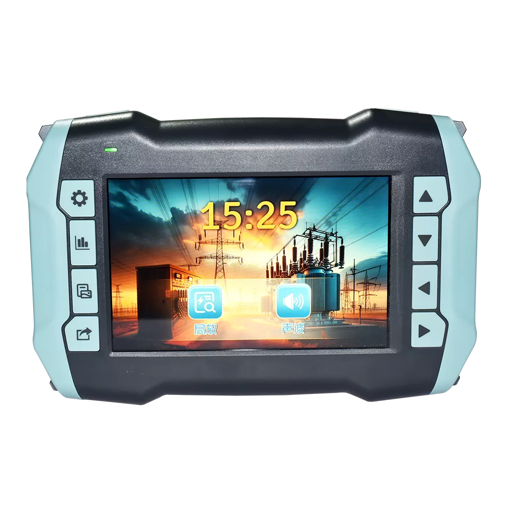
11.Industrial-Grade Hardware
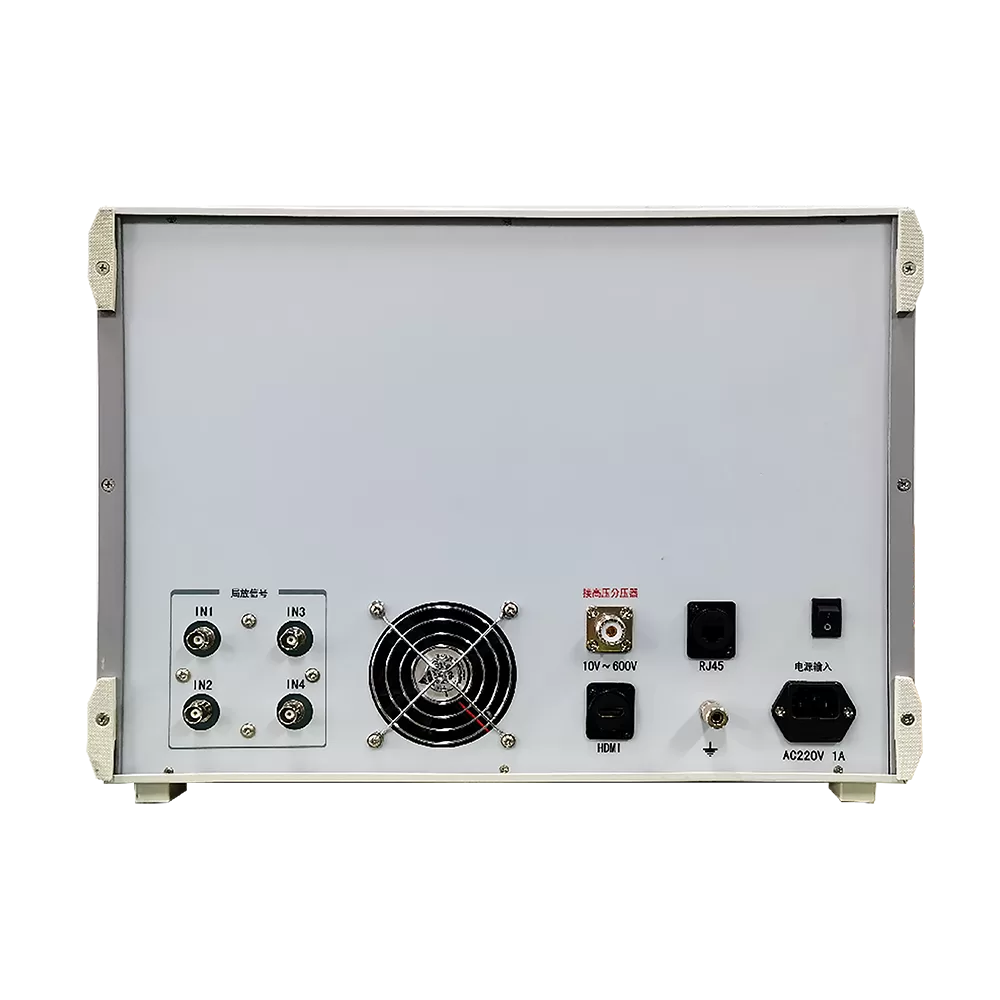
Equipped with a high-brightness, 15-inch (or larger) LCD touchscreen display (1280×1024) and a comprehensive array of interfaces (USB, RJ45, HDMI, etc.), making it ideally suited for industrial field environments.
12.Standards Compliance
Fully compliant with domestic and international partial discharge measurement standards, including IEC 60270, GB/T 7354, DL/T 417, and others.
Parameter
| Main Technical Parameters | ||
| Measurement Channels | Four independent channels | |
| Capacitance Range of Test Specimens | 6 pF to 250 μF | |
| Measurement Range | 0.1 pC to 10,000 nC | |
| Detection Sensitivity | 0.01 pC | |
| Sampling Accuracy | 12-bit; Sampling Rate: 20 MS/s | |
| Display Modes | Display Methods | Ellipse — Sine Wave — Straight Line |
| Trigger Synchronization Modes | Internal and External. Internal triggering synchronizes with the instrument’s power supply (50 Hz); external triggering synchronizes with the operating frequency of the test power supply (any frequency within the range of 50 Hz to 400 Hz). | |
| External Trigger Synchronization Signal Input Voltage | 10 V to 200 V; Input Power: <1 VA | |
| Signal Phase Determination | The ellipse display utilizes a polar coordinate mode, while the sine wave display utilizes a sinusoidal mode. The starting point of the displayed waveform corresponds to the zero-crossing point of the test power supply, and the length of the waveform corresponds to one full cycle of the test power supply. Under the external trigger synchronization mode, the system accurately and precisely displays the cycle and phase of the test power supply. | |
| Time Window | The phase range is freely selectable; the time window display can be dynamically magnified. The four time windows can be enabled individually or simultaneously | |
| Filter Bandwidth | The 3 dB low-frequency cutoff (fL) offers settings of 20, 40, 60, and 80 kHz, plus an OFF setting (9 kHz). The 3 dB high-frequency cutoff (fH) offers settings of 100, 200, 300, and 400 kHz, plus an OFF setting (1 MHz). fL and fH can be flexibly combined to create various filter passbands. Digital Filtering: Freely selectable within the range of 10 kHz to 1 MHz | |
| Signal Amplifier | Gain Adjustment | Comprises both Coarse Gain Adjustment and Fine Gain Adjustment. Coarse gain offers 5 steps, with a 20 dB (10-fold) gain difference between steps and an adjustment error of ±1 dB. Fine gain adjustment range: >20 dB |
| Amplifier Asymmetry in Positive/Negative Polarity Response | <1 dB | |
| Partial Discharge Signal Measurement | Partial discharge signals can be measured in various display modes, including continuous and amplified modes, with an accuracy of ±5% (relative to full scale) | |
| Operating Environment | Ambient temperature: -10°C to 45°C; Relative humidity: ≤95% | |
| Power Supply | AC 220V; Frequency: 50 Hz; Power Consumption: 100 W (utilizing a 300 W industrial-grade power supply) | |