Features and Advantages
1.Once a gas leak occurs, the acoustic imaging module can sense the ultrasonic/acoustic waves generated when the gas leaks, so as to locate the location of the leak and give an alarm. The realization of this function is based on acoustic imaging technology, using a microphone array, scanning space sound waves, and determining the fault location through the phase difference of sound waves to obtain an “acoustic image”.
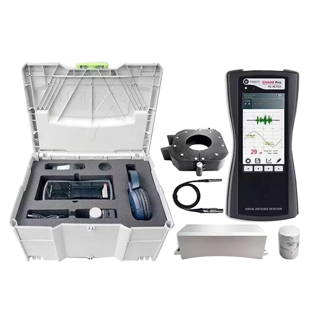
2.Automatic diagnosis and analysis of test results, with independent data acquisition and partial discharge signal analysis and diagnosis functions. It can also provide sensor test data and important data such as time domain/PRPD/PRPS map/histogram/time-of-flight map.
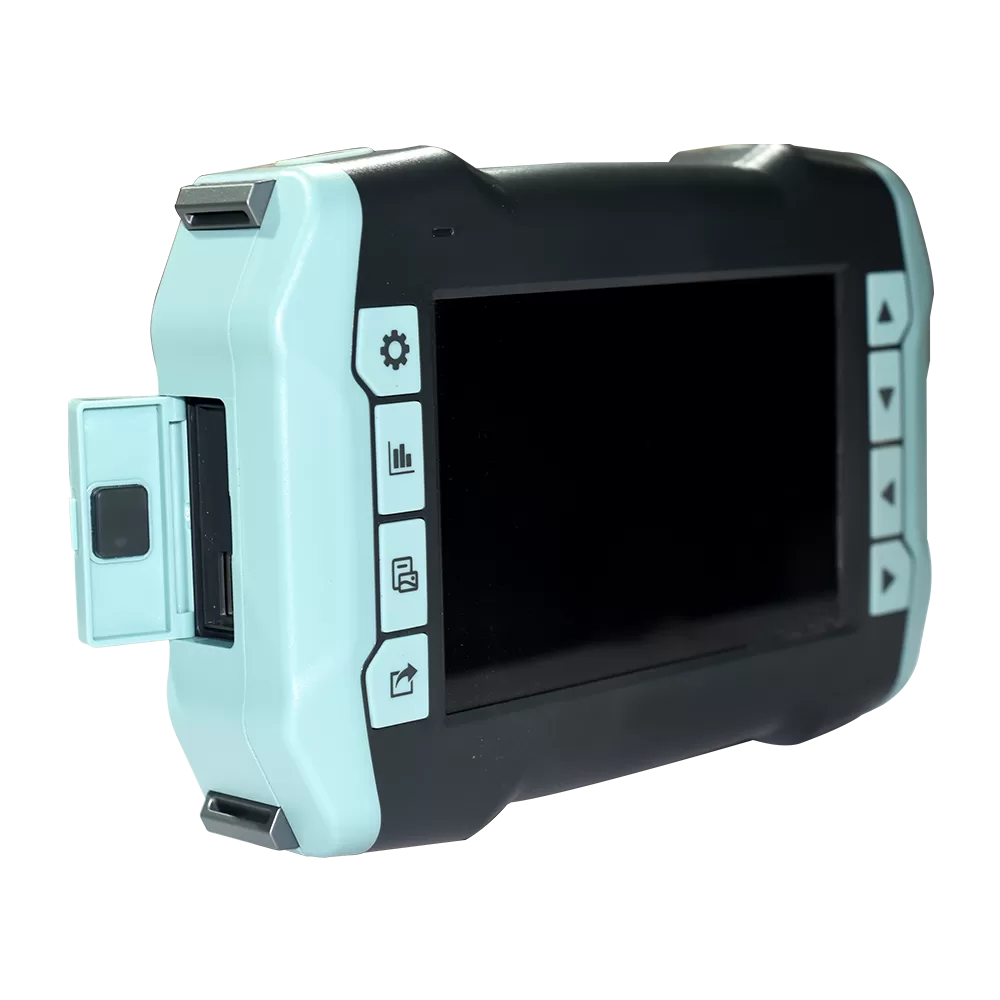
3.Wireless WiFi or Bluetooth connection; USB or Bluetooth export test report, Bluetooth playback audio function
4.Configure different sensors to realize the partial discharge detection of almost all high-voltage electrical equipment;
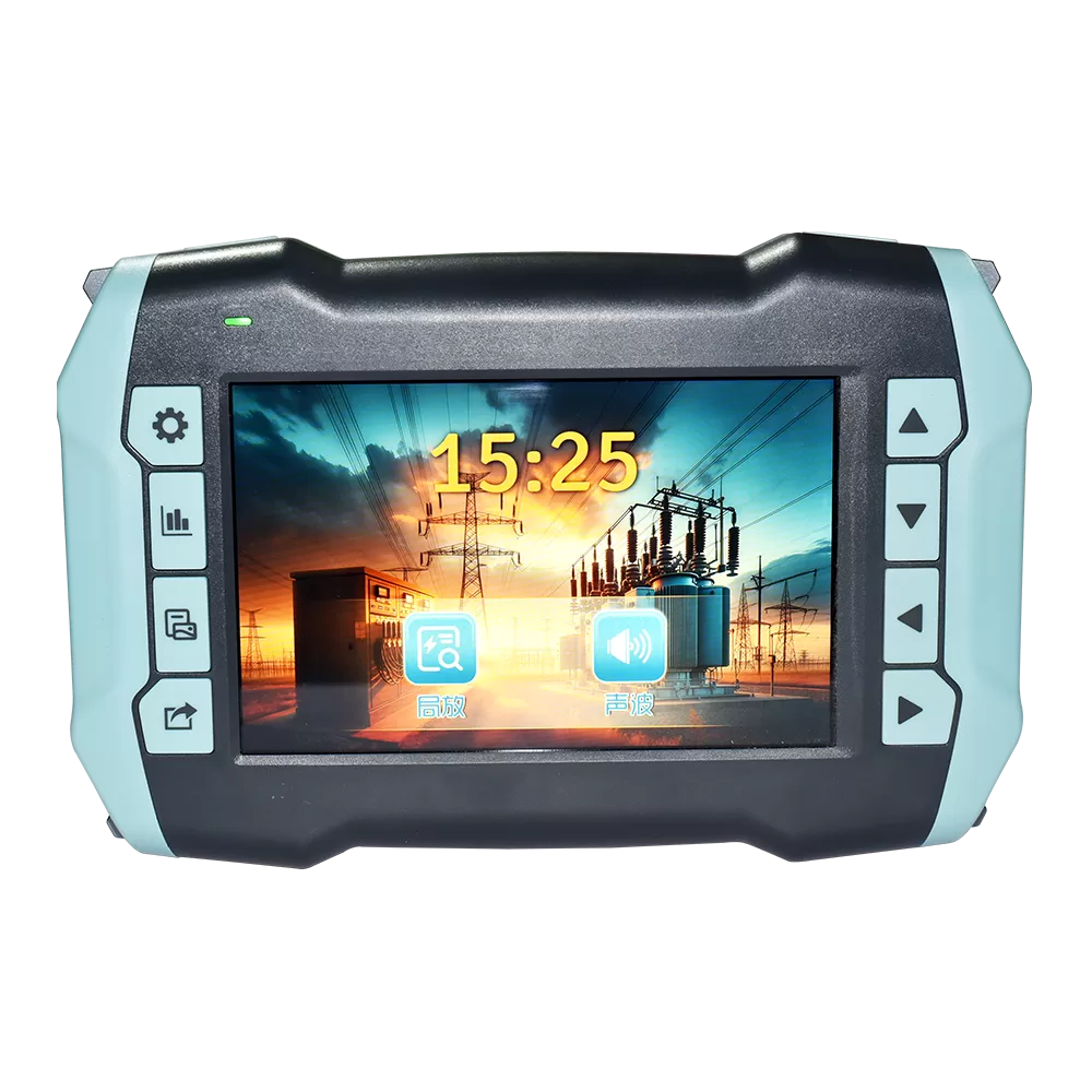
5.Button/touch screen control. Humanized man-machine interface facilitates data management of different devices;
6.Multi-function PD Collector – WiFi version of the precision small structure, accurate data acquisition and diversified measurement principles, can realize the partial discharge detection of various electrical equipment, including ultrasonic, ground wave measurement principle. You only need to change the different sensors, and you can perfectly solve the task of partial discharge detection of high-voltage electrical equipment. It can be connected to special detection sensors such as GIS, transformers, overhead lines, cables, etc.
7.The non-invasive detection method does not require power failure during the test process, and there is no need to configure an additional high-voltage source, which is more convenient to use than the traditional pulsed partial discharge detector;
8.The test bandwidth range is 30kHz ~ 3.0GHz, which is suitable for the detection principle of various frequency bands;
9.By using the image color display and hot spot tracking display function displayed on the screen, it is possible to preliminarily determine the heat condition and fault location, so that the problem can be identified with high efficiency and high accuracy.
10.It can take photos, record screens, and display 30-day historical data trend charts.
Parameter
| Geoelectric Wave Parameters | Contact Ultrasonic Parameters | ||
| Measurement range | 0~80 dBmV | Measurement range | -8dB μV ~ 80dB μV |
| Resolution | 0.1dB | Resolution | 0.1dB |
| Accuracy | ±1dB | Accuracy | ±1dB |
| Maximum pulse per cycle | 1400 | Frequency range | 20~500 kHz |
| Measurement band | 3~100MHz | ||
| Non-Contact Ultrasonic Parameters | |||
| Measurement range | -8dBμV~80dBμV | Detection frequency band | 300MHz~3000MHz |
| Resolution | 0.1dB | Measurement range | -80 ~ -10dBm |
| Accuracy | ±1dB | ||
| Sensor center frequency | 40 kHz ± 2kHz | ||
| High Frequency Transformer Parameters | Acoustic Sensor Parameters | ||
| Sensor transmission impedance | 9.9mV/mA | Frequency range | 0~48kHz |
| Detection frequency | 0.5~50MHz(Customizable) | Measurement distance | 0.3~50m |
| Sensitivity | 1mV | Number of microphones | 64~128 pcs |
| Inspection range | 0~3000 mV | Camera field of view | 58°* 27° |
| Infrared Camera High Configuration (Optional) | Infrared Camera High Configuration (Optional) | ||
| Resolution | 640×512 | Resolution | 384×288 |
| Temperature measuring range | -20℃ ~+550℃ | Temperature measuring range | -20℃~400℃ |
| Accuracy of temperature measurement | ±3℃ | Accuracy of temperature measurement | ±2℃ |
| Ambient temperature | -20℃~60℃ | ||
| Infrared Camera Low Configuration (Optional) | Wave converter | ||
| Resolution | 256×192 | Measurement range | -8dBμV~80dBμV |
| Temperature measuring range | -10℃~150℃ | Measure distances | 0m~100m |
| Accuracy of temperature measurement | ±3℃ | Sensor center frequency | 40 kHz ± 2kHz |