
What are the respective functions of binary inputs and binary outputs in a relay protection tester?
What are the respective functions of binary inputs and binary outputs in a relay protection tester?
The terms “binary input” (or “switch input”) and “binary output” (or “switch output”) frequently appear in the specifications of relay protection testers. When purchasing or using these testers, users often focus on voltage/current output and the number of channels, while overlooking the importance of binary inputs and outputs. In reality, however, binary inputs and outputs are directly linked to measuring operation time, verifying tripping logic, and testing automatic control devices.
1. Binary inputs (also known as switch inputs) are primarily used to receive external contact signals. During relay protection testing, a protection device typically outputs signals via tripping, closing, alarm, or operation contacts after it operates. By connecting these contacts to the tester’s binary inputs, the tester can determine whether the protection has operated and record the operation time.
For example, when testing overcurrent protection, the tester outputs a fault current to the protection device. Once the protection device operates, the tripping contact closes or opens; the tester receives this signal via the binary input and automatically records the time elapsed between the application of the fault quantity and the operation. This allows for the verification of whether the protection operation time meets the specified settings.
Binary inputs are used not only for measuring operation time but also for determining the operational status of the protection. In tests such as reclosing, automatic bus transfer, synchronization, differential protection, and distance protection, the tester must proceed to the next stage of the test sequence based on contact status feedback from the protection device or circuit breaker. Therefore, a higher number of binary inputs makes the tester more suitable for testing complex logic.
2. Binary outputs (also known as switch outputs) are primarily used to provide simulated contact signals to external equipment. They can simulate various states, such as circuit breaker positions, blocking signals, start signals, remote signals, and closing permission signals. In tests involving automatic control devices and complex protection schemes, voltage and current outputs alone are insufficient; binary outputs are required to simulate actual field operating conditions.
For instance, when testing the automatic bus transfer function, the tester may need to simulate conditions such as the incoming line circuit breaker being closed, the bus-tie circuit breaker being open, a loss of voltage on the main power supply, and the presence of voltage on the backup power supply. Some conditions can be simulated via voltage outputs, while other states—such as circuit breaker position or interlocking contacts—require the use of binary outputs. The automatic transfer device will only operate according to its programmed logic when these conditions are met.
For instance, when testing reclosing functions, the system must verify the circuit breaker’s open position after the protection device trips; it then decides whether to reclose based on conditions like “dead-bus check” (voltage absence) or “synchro-check” (synchronization). In this scenario, the relay test set uses binary outputs to simulate signals such as the circuit breaker’s open and closed positions, working in tandem with voltage outputs to execute a complete test of the reclosing logic.
Simply put, binary inputs are for “receiving signals,” while binary outputs are for “sending signals.” Binary inputs receive feedback on the protection device’s operation, whereas binary outputs simulate the status of external contacts. Only by using both together can one perform tests on operation timing, logic, output contacts, and integrated automatic device systems.
3. When purchasing a relay test set, assess whether the number of binary inputs and outputs is sufficient for your testing requirements. Basic protection tests—such as overcurrent, undervoltage, or underfrequency—can usually be handled with a limited number of binary inputs. However, frequent testing of automatic transfer schemes, reclosing, synchro-check, fast bus transfer, multi-breaker logic, or complex automation devices requires a higher number of binary inputs and outputs.
When using binary inputs, pay attention to the contact type. Field contacts may be “dry” (potential-free) or “wet” (live/voltage-carrying). Before wiring, verify the input modes supported by the test set and follow the manual’s instructions for correct connection. Incorrect binary input settings may prevent the test set from recording operation times, potentially leading to the false conclusion that the protection device failed to operate.
When using binary outputs, consider contact capacity and circuit voltage. Binary outputs are generally intended to simulate contact signals; do not connect them to live circuits that exceed their rated capacity. Before wiring, confirm the output contact type and the permissible voltage and current ranges to avoid damaging the test set or field equipment.
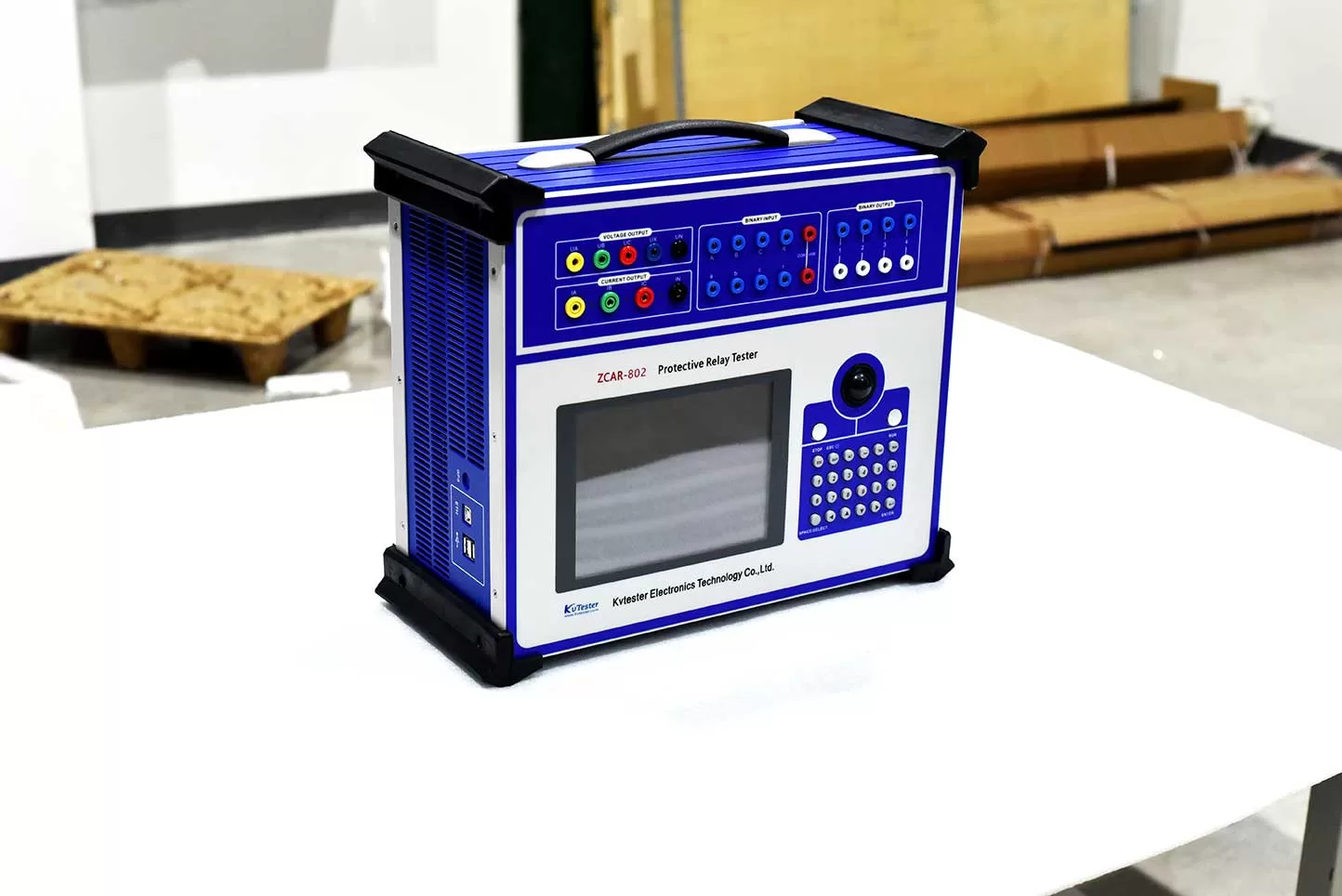
4. During field testing, if the test set fails to record an operation time, prioritize checking the binary input wiring: verify whether the connection uses normally open (NO) or normally closed (NC) contacts and ensure the trigger mode settings match the actual configuration. If the automated test sequence fails to proceed to the next state, verify whether the binary outputs correctly simulate the circuit breaker position, interlocking signals, or initiation conditions.
In summary, although the binary inputs and outputs of a relay test set are not as immediately intuitive as voltage and current outputs, they play a crucial role in relay protection testing. Binary inputs are used to receive protection operation signals, while binary outputs simulate external status signals. For the testing of complex protection schemes and automatic devices, the number of binary inputs and outputs—as well as the wiring configuration—directly impacts testing efficiency and the accuracy of the results.
Related Products





Latest News
-
 2026-09-24How to quickly troubleshoot a failure of the protection device to operate during relay protection testing?
 -
 2026-09-24How to Read a DC Resistance Tester Specification for Transformer Testing?
 -
 2026-09-24How Does a Variable Frequency Relay Tester Test Over/Underfrequency Relays?
 -
 2026-09-23How Can You Choose the Right Multi-Function Variable Frequency PT Tester Supplier?
 -
 2026-09-23What Features Should a Resistance Tester for Transformer Factory Have?
