Home » News » Company News
Variable Inductance Resonant Test System: How It Works
A variable inductance resonant test system is designed for high-voltage AC withstand testing when the test frequency needs to remain at a specified value. Instead of relying primarily on frequency adjustment, it changes the reactor inductance to establish resonance with the capacitance of the test object.
This approach is useful for testing large-capacity electrical equipment, including generators, GIS, and power transformers. By matching the reactor inductance to different capacitive loads, the system can generate the required high AC voltage while reducing the power capacity required from the input supply.
Understanding how the adjustable reactor works, how it differs from a variable-frequency system, and how to select the right configuration can help testing teams choose suitable equipment for their applications.
What Is a Variable Inductance Resonant Test System?
A variable inductance resonant test system is a high-voltage testing solution that uses an adjustable reactor to form a series resonant circuit with the capacitance of the test object.
Its main purpose is to generate the required AC test voltage while reducing the input power capacity needed for high-voltage testing.
A typical system consists of several components:
- Adjustable reactor: Changes the inductance of the resonant circuit to match different test loads.
- Excitation transformer: Supplies the voltage required to establish resonance.
- Voltage regulator: Controls the input voltage supplied to the excitation transformer.
- Capacitive voltage divider: Measures the high voltage applied to the test object.
- Control system: Controls voltage and inductance adjustment and monitors operating parameters and protection conditions.
The adjustable reactor is the defining component. Depending on the system design, its inductance can be changed to accommodate different test capacitances without requiring operators to rely exclusively on frequency adjustment.
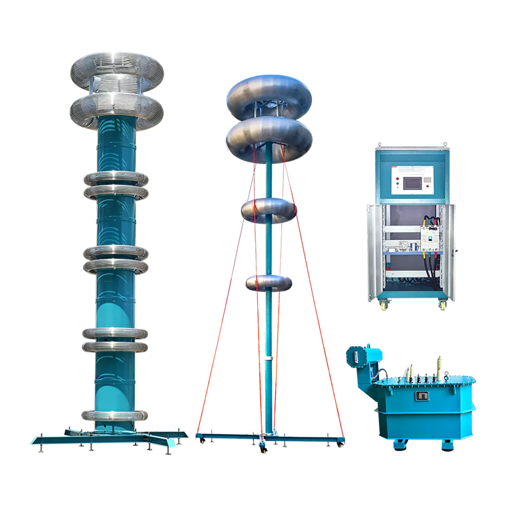
Kvtester’s ZCVF-C Inductance-Tuned Power-Frequency Resonant Test System is one example. It uses power-frequency series resonance technology and an adjustable reactor configuration for high-voltage AC withstand testing.
How Does Variable Inductance Control the Resonant Condition?
The operating principle is based on series resonance between an inductor and a capacitor.
The resonant frequency is calculated using:
Resonant Frequency (f₀) = 1 / (2π × √(L × C))
Where:
- (f_0) is the resonant frequency.
- (L) is the inductance of the reactor.
- (C) is the equivalent capacitance of the test object.
When the inductive reactance and capacitive reactance are equal, the circuit reaches series resonance.
In a power-frequency variable inductance system, the test frequency is generally maintained at the required value, such as 50Hz, while the reactor inductance is adjusted to match the capacitance of the test object.
Adjusting Inductance to Match Different Loads
The capacitance of a test object determines the inductance required to establish resonance at a given frequency.
For example, suppose a test system needs to operate at 50Hz. If the capacitance of the next test object differs from that of the previous one, the reactor inductance must be adjusted accordingly.
A larger capacitance requires a smaller inductance to maintain the same resonant frequency. Conversely, a smaller capacitance requires a larger inductance.
This relationship allows one system to accommodate different capacitive loads within its designed adjustment range.
How Does an Adjustable Reactor Change Inductance?
An adjustable reactor changes its effective inductance by modifying its magnetic circuit.
One practical method is to adjust the air gap in the reactor’s magnetic structure. Changing the air gap changes the magnetic reluctance and therefore the inductance.
The adjustment mechanism varies by equipment design. For example, the ZCVF-C-320kVA/320kV Resonant Voltage Boost Device uses air-gap shims of different thicknesses to adjust reactor inductance according to the capacitance of the test object.
Its individual reactor has an inductance adjustment range of 70H–550H, with a rated withstand voltage of 40kV and capacity of 40kVA.
This is a specific adjustment method for this product configuration. Other adjustable reactor systems may use different mechanisms, so the adjustment method should always be checked against the actual equipment specifications.
Why Is Variable Inductance Important for Power-Frequency Testing?
Not every high-voltage AC withstand test uses the same frequency requirements. The appropriate test frequency depends on the test object and the applicable testing procedure.
When a test requires a specified power frequency, changing the power supply frequency may not be the preferred approach. A variable inductance system provides another way to establish resonance.
Maintaining a Specified Test Frequency
In a 50Hz power-frequency resonant test, the system can maintain the output frequency at 50Hz while adjusting reactor inductance to match the test object’s capacitance.
This is useful when the testing procedure specifies power-frequency voltage rather than allowing a wider frequency range.
The adjustable reactor therefore provides flexibility in load matching without relying on frequency changes as the primary tuning method.
Adapting to Different Test Capacitances
Different test objects have different equivalent capacitances. Even equipment of the same general type may present different loads because of variations in rated capacity, winding structure, or test connections.
A suitable inductance adjustment range helps the system accommodate these differences.
This is particularly relevant when testing large generator stator windings and other capacitive high-voltage equipment. The reactor configuration must match the actual capacitance of the test object while meeting the required test voltage and frequency.
Reducing the Required Input Power
At series resonance, the inductive and capacitive reactive voltages balance each other. The power supply mainly needs to compensate for active losses in the resonant circuit rather than provide the full reactive power required by the test object directly.
The quality factor (Q) describes the voltage magnification in the resonant circuit. Under suitable operating conditions, the voltage across the test object can be much higher than the excitation voltage.
This makes series resonance a practical method for generating high AC test voltages without requiring an input power supply with the same capacity as a conventional direct high-voltage source.
Variable Inductance vs. Variable Frequency Resonant Test Systems
Both systems use the same basic LC series resonance principle. Their main difference lies in how they adjust the resonant condition.
Variable Inductance System
A variable inductance system primarily adjusts the reactor inductance while maintaining the specified test frequency.
Its main characteristics include:
- Power-frequency operation, such as 50Hz.
- Adjustable reactor inductance for matching different test capacitances.
- Inductance adjustment through the reactor’s designed mechanism.
- Suitability for applications with specific frequency requirements.
The main consideration is the available inductance adjustment range. The reactor must cover the required load conditions.
Variable Frequency System
A variable-frequency resonant test system generally uses a selected reactor configuration and changes the power supply frequency to find the resonance point.
Variable-frequency systems are used for AC withstand testing of power cables, transformers, GIS, and other high-voltage equipment, depending on the specific system configuration.
Which Adjustment Method Should You Choose?
Neither method is universally better. The choice depends on the test frequency requirements, load capacitance, reactor configuration, and intended application.
A variable inductance system is worth considering when power-frequency operation is required and the test loads vary within the reactor’s adjustment range.
A variable-frequency system may be more suitable when the test procedure permits frequency variation and a broader range of load conditions needs to be covered.
Some systems may combine different adjustment methods, but this should be confirmed from the actual equipment configuration rather than assumed from the product category.
Which High-Voltage Equipment Can Be Tested with a Variable Inductance Resonant System?
The suitable application depends on the system’s rated voltage, current, capacity, inductance range, and test frequency.
Variable inductance systems are particularly relevant to large-capacity equipment that requires power-frequency AC withstand testing.
Generator Stator Winding Testing
Generator stator windings have distributed capacitance, and their equivalent capacitance varies with generator design and rated capacity.
A variable inductance resonant system can adjust the reactor to match this capacitance while maintaining the specified power-frequency test condition.
The ZCVF-C series is primarily designed for AC withstand voltage testing of hydraulic generators with individual unit capacities of up to 250MW. Its product specifications also list configurations for thermal generator testing.
This illustrates why reactor adjustment range and the actual capacitance of the generator winding are important when selecting a system.
GIS, Voltage Transformers, and Power Transformers
Adjustable inductance resonant systems can also be configured for other high-voltage applications.
Adjustable reactor systems are not limited to generator testing. However, the rated voltage, load capacitance, and reactor configuration must match the specific test object.
What Determines the Configuration of a Variable Inductance Resonant Test System?
Selecting a system based only on its maximum output voltage can lead to an unsuitable configuration. The test object and its electrical parameters determine the reactor arrangement and overall system capacity.
Rated Test Voltage
Start with the required AC withstand test voltage. Consider the rated voltage of the test object, the applicable test procedure, and the required test duration.
The system’s rated output voltage must cover the required test level under the intended operating conditions.
Load Capacitance and Inductance Range
The equivalent capacitance of the test object is one of the most important parameters.
At a specified frequency, the required inductance can be calculated from the resonance equation. The adjustable reactor must cover this required value.
If the load capacitance varies significantly between test objects, a wider inductance adjustment range may be necessary.
Test Current and System Capacity
The required capacitive current is related to the test voltage, frequency, and capacitance:
Capacitive Current (I) = 2 × π × f × C × U
Where:
- (I) is the capacitive current.
- (f) is the test frequency.
- (C) is the test object’s capacitance.
- (U) is the test voltage.
The required reactive capacity can then be estimated from:
Required Reactive Capacity (S) = Test Voltage (U) × Test Current (I)
Where:
- S is the required reactive capacity (VA or kVA).
- U is the applied test voltage (V or kV).
- I is the required test current (A).
These calculations help determine the reactor rating, excitation transformer capacity, and overall system configuration.
Reactor Configuration and Portability
An adjustable reactor can reduce the need to connect multiple fixed reactors in series or parallel during different tests. This may simplify field operation.
However, adjustable reactors can still be large and heavy, particularly in high-voltage and high-capacity applications. A combination of fixed and adjustable reactors may be more practical for certain load ranges.
Consider the available installation space, transportation conditions, reactor arrangement, and frequency of equipment relocation before making a decision.
Control and Protection Functions
The control system should support reliable voltage and inductance adjustment and provide clear monitoring of operating conditions.
Important functions to evaluate include:
- Inductance adjustment and position monitoring.
- Test voltage and current monitoring.
- Overvoltage and overcurrent protection.
- Zero-position start protection, where provided.
- Detuning and flashover protection.
For example, the ZCVF-C series supports voltage and inductance adjustment and monitors parameters such as power factor, high-voltage current, test voltage, and air-gap position. Its product specifications also describe overcurrent and overvoltage protection.
How to Prepare for a Variable Inductance Resonant Test
Correct preparation helps the system reach resonance safely and maintain stable test conditions.
A typical testing procedure includes the following steps:
- Confirm the test parameters. Identify the test object’s capacitance, required voltage, frequency, and test duration.
- Check the equipment configuration. Verify that the reactor, excitation transformer, voltage divider, and control system match the test requirements.
- Complete the electrical connections. Connect the test object and system components according to the manufacturer’s instructions. Check grounding and high-voltage clearances.
- Adjust the reactor inductance. Use the equipment’s designed adjustment mechanism to bring the circuit toward the required resonant condition.
- Raise the test voltage gradually. Monitor voltage, current, and system operating conditions throughout the process.
- Complete the test and record results. Follow the applicable test procedure, then discharge and ground the test object after testing.
The exact operating sequence depends on the equipment design. For example, a reactor adjusted using air-gap shims requires a different adjustment procedure from a system with a motorized mechanism. Operators should always follow the manufacturer’s instructions and relevant safety procedures.
Choosing the Right Variable Inductance Resonant Test System
A variable inductance resonant test system is particularly valuable when high-voltage AC testing requires a specified power frequency and the test load capacitance varies.
Its adjustable reactor provides a practical way to match different capacitive loads without relying solely on power supply frequency adjustment. However, the right system still depends on the test voltage, load capacitance, required current, inductance range, and application.
At Kvtester, we provide resonant test solutions for different high-voltage testing requirements, including power-frequency inductance-tuned systems and variable-frequency series resonant systems.
If you are planning generator stator winding testing, GIS testing, or another high-voltage AC withstand test, share your test object, rated voltage, capacitance, and required test frequency with our team.
Contact us to discuss your application and get a suitable resonant test system configuration.
Related Products
Latest News
-
 2026-11-20How to Use a PT Tester for Accurate Error Calibration
-
 2026-11-20High Voltage PT Tester for Accurate Voltage Transformer Testing
-
 2026-11-19Generator Rotor AC Impedance Tester for Fault Detection
-
 2026-11-19Anti-interference Transformer Tester for Substation
-
 2026-11-19How Does a CT Tester Work? Understanding Its Working Principle