
How to quickly troubleshoot a failure of the protection device to operate during relay protection testing?
How to quickly troubleshoot a failure of the protection device to operate during relay protection testing?
Failure of the protection device to operate is a common issue encountered during field relay protection testing. Even though the test set outputs the required voltage, current, or fault quantities, the protection device may fail to start or trip, or the test set may fail to record an operation signal. Such situations do not necessarily indicate a device malfunction; they could also stem from issues with settings, wiring, terminal links (straps), blocking conditions, or test set configurations.
When faced with a failure to operate, it is not advisable to repeatedly increase the current or voltage in a forced attempt to trigger the device. Instead, a systematic troubleshooting approach should be adopted—checking the output first, followed by wiring, settings, and finally logic—to avoid misjudgment or increased operational risk.
① First, verify that the relay protection test set is outputting signals correctly.
Test personnel should check the test set’s software interface, output indicators, and the values displayed on the protection device to confirm that voltage, current, frequency, and phase quantities are correctly applied to the device. If the test set is configured to output signals but the protection device does not display the corresponding electrical quantities, priority should be given to checking test leads, terminal connections, output channel selection, and circuit continuity.
② Check if the test parameters are set correctly.
Different protection functions require specific test conditions. For instance, overcurrent protection requires the current to exceed the set value; undervoltage protection requires the voltage to drop below the operation threshold; distance protection requires voltage, current, and phase to satisfy impedance conditions; and directional protection requires the correct power direction. If the test set’s output does not meet the criteria for protection operation, the device will naturally not operate.
③ Verify the protection settings and ensure the protection functions are enabled.
Common field issues include protection functions, software links, or hardware links not being enabled; incorrect setting group selection; or specific protection stages not being activated. Before testing, confirm the active setting group, protection control words, protection links, and the status of protection functions to prevent testing against one set of parameters while the device is actually operating under another.
④ Check the correctness of the binary input (contact input) wiring.
Sometimes the protection device operates, but the test set fails to record the operation time. This may occur because the protection device’s output contact is not correctly connected to the test set’s binary input, or because the binary input type is configured incorrectly. Test personnel must verify whether the contact being connected is a trip contact, operation contact, or alarm contact, and determine whether it is a dry contact (potential-free) or a live contact, ensuring wiring is performed correctly according to the tester’s requirements.
⑤ Check for the presence of protection blocking conditions.
Many protection functions do not operate immediately upon current or voltage reaching set values; they may be subject to blocking conditions. For example, under-frequency protection may have undervoltage blocking; auto-reclosing may have a blocking signal; distance protection may have PT circuit-break blocking; differential protection may have harmonic blocking; and automatic bus transfer (ABT) may be constrained by circuit breaker positions or busbar voltage conditions. If a blocking condition exists, the protection will not operate as expected.
⑥ Check current and voltage phase identification and phase relationships.
For simple overcurrent protection, incorrect phase identification may prevent the target protection stage from triggering; for functions such as directional, distance, and differential protection, incorrect phase relationships directly affect the protection’s decision-making. If test results are abnormal, prioritize verifying the wiring, polarity, phase sequence, phase angle settings, and CT/PT ratios for phases A, B, and C.
⑦ Review the protection device’s event records and real-time values.
Protection devices typically record events such as startup, blocking, operation, and alarms. By examining event reports, remote signaling status, binary input status, and real-time sampled values, one can quickly determine whether the protection received the test signal and whether it failed to operate due to an unmet condition.
⑧ Check the trip output and secondary circuits.
If the protection device has operated internally but no trip signal is received on-site, the cause could be an unengaged output link (test switch), a disconnected trip circuit, a faulty output relay, or a secondary wiring issue. In this case, distinguish between “protection logic did not operate” and “protection operated but the output signal was not sent,” as the troubleshooting approaches differ for these two scenarios.
⑨ Check whether the testing method aligns with the protection principles.
For instance, when testing differential protection, injecting current from only one side may fail to correctly simulate restraint characteristics; when testing distance protection, incorrect impedance point or fault type settings may prevent operation; and when testing under-frequency protection, a frequency variation pattern that does not match the device’s criteria may lead to abnormal operation.
⑩ Troubleshoot potential faults in the protection device or the test instrument itself. If the protection fails to operate after verifying settings, wiring, terminal links, blocking conditions, and parameters, you can try switching test channels or test leads, or use alternative test methods for cross-verification. If necessary, check the protection device’s self-test logs, alarm status, and sampled values.
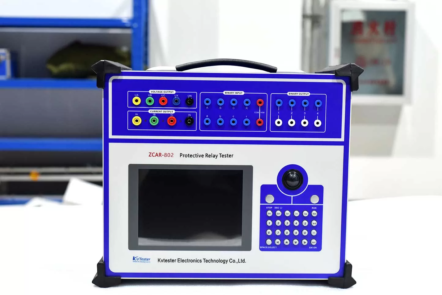
Common reasons for a protection device failing to operate during testing include: incorrect test set output; wiring errors (test leads or terminals); mismatched protection settings; protection functions or terminal links not being enabled; incorrect binary input connections; uncleared blocking conditions; phase or polarity errors; faults in the protection output circuit; or a mismatch between the testing method and the protection logic.
In summary, if the protection fails to operate during testing, first verify that the test set’s output matches the values displayed by the protection device, then check the settings, terminal links, wiring, binary inputs, and blocking logic. Do not conclude that the protection device is faulty simply because it failed to trip. Following a systematic troubleshooting process allows for faster problem identification and reduces on-site risks associated with incorrect wiring, operational errors, and redundant testing.
Related Products





Latest News
-
 2026-09-24What are the respective functions of binary inputs and binary outputs in a relay protection tester?
 -
 2026-09-24How to Read a DC Resistance Tester Specification for Transformer Testing?
 -
 2026-09-24How Does a Variable Frequency Relay Tester Test Over/Underfrequency Relays?
 -
 2026-09-23How Can You Choose the Right Multi-Function Variable Frequency PT Tester Supplier?
 -
 2026-09-23What Features Should a Resistance Tester for Transformer Factory Have?
