What are the differences in equipment configuration for comprehensive test benches designed for 10kV, 20kV, and 35kV transformers?
What are the differences in equipment configuration for comprehensive test benches designed for 10kV, 20kV, and 35kV transformers?
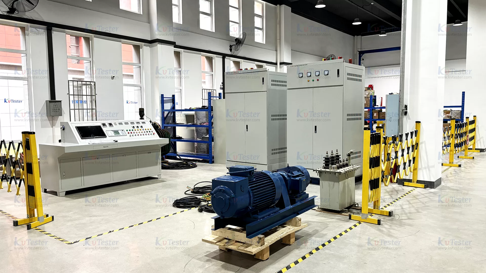
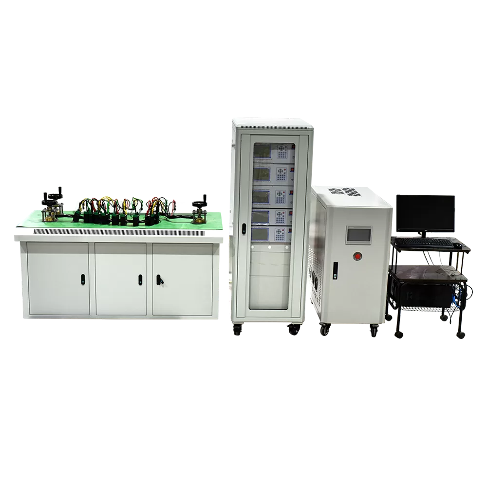
While the fundamental testing principles for 10kV, 20kV, and 35kV transformer comprehensive test benches are the same—all capable of performing tests such as no-load loss, load loss, short-circuit impedance, DC winding resistance, turns ratio and vector group, and insulation withstand voltage—the equipment configuration must be tailored to each voltage class. Key areas requiring specific adjustments include withstand voltage output capacity, insulation levels, measurement ranges, test power supply specifications, and safety protection measures.
It is important to note that the voltage class primarily dictates the requirements for insulation testing, whereas the transformer capacity directly influences the selection of voltage regulators, test power supplies, and current transformers.
1. Key Configuration Differences Across Voltage Classes
The following comparison is based on standard factory acceptance testing for 50Hz power transformers.
| Comparison Item | 10 kV Transformer | 20 kV Transformer | 35 kV Transformer |
| Highest Voltage for Equipment (Um) | 12 kV | 24 kV | 40.5 kV |
| Reference Separate-Source AC Withstand Voltage for Oil-Immersed Transformers | 35 kV | 55 kV | 85 kV |
| Power-Frequency Withstand Voltage Test Equipment | Consider 50 kV class | Consider 75 kV class | Consider 100 kV class |
| No-Load and Load Test System | Standard configuration | Match transformer rating and winding voltage | Prioritize wide measurement range and high-capacity compatibility |
| Voltage Regulator and Test Power Supply | Select based on transformer rating | Select based on transformer rating | Large-capacity units under test may require a higher-rated power supply or compensation |
| Turns Ratio and DC Winding Resistance | Standard measurement modules | Extended measurement range | Select based on turns ratio, winding resistance, and required test duration |
| Induced Voltage Withstand Test System | Select a variable-frequency power supply to suit the unit under test | Verify excitation voltage and power rating | Focus on power supply capacity and insulation coordination |
| Safety and Protection | Basic HV interlocking and protection | Enhance insulation capability for the corresponding voltage class | Strengthen HV isolation, interlocking, and monitoring |
In the table, the values 35kV, 55kV, and 85kV represent the applied withstand voltage test levels for oil-immersed transformers, as specified in standards GB/T 1094.3-2017 and JB/T 501-2021; these do not represent the rated output voltage of the test bench itself. The power-frequency withstand voltage equipment ranges provided are preliminary selection examples; final specifications must be verified against required output current, capacity, and safety margins. For dry-type transformers, as well as for on-site commissioning or preventive maintenance testing, configurations should be determined in accordance with the relevant applicable standards.
2. Configuration Variations by Test Module
①. No-Load and Load Loss Testing System
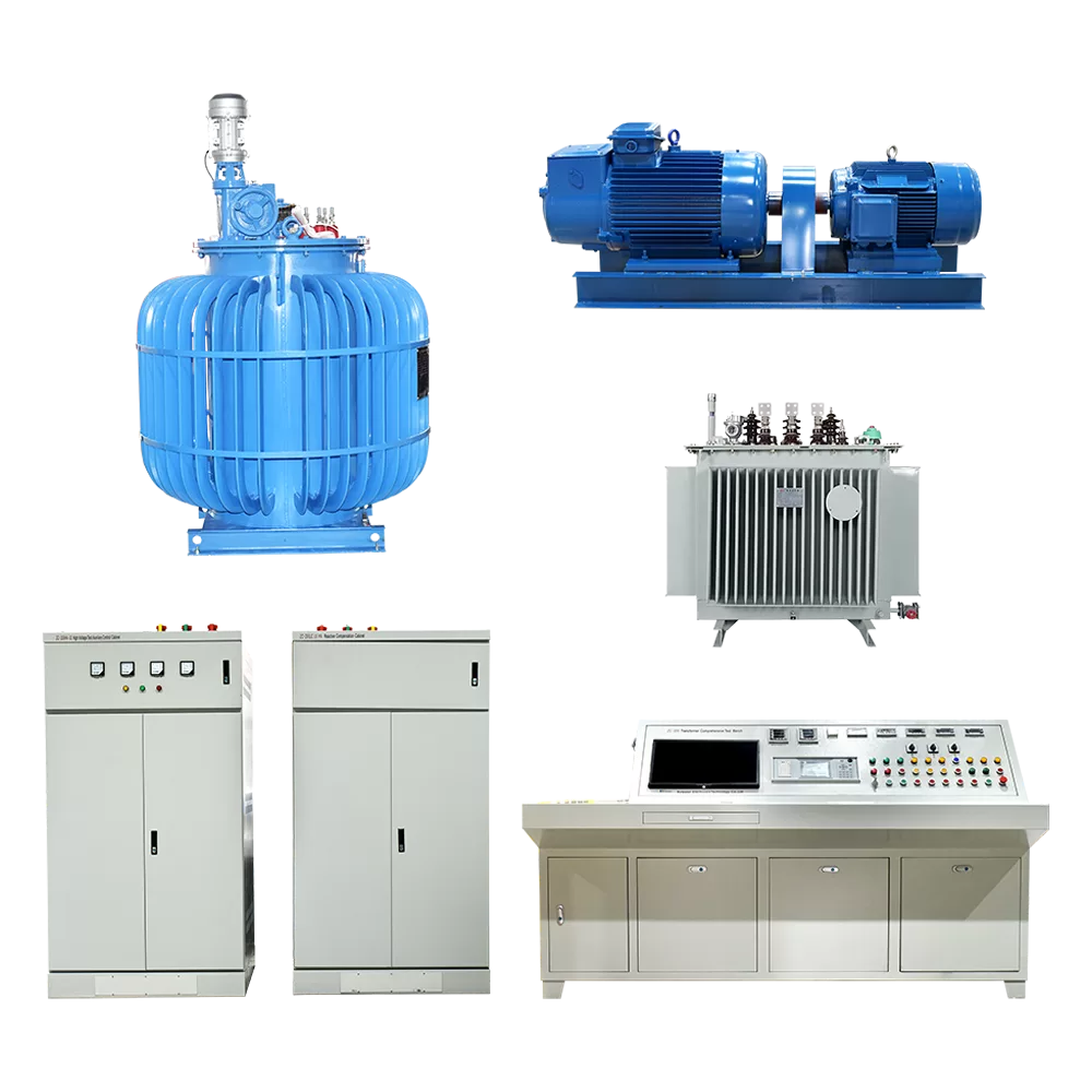
For 10kV, 20kV, and 35kV transformers, the measurement system can be constructed using a three-phase power analyzer, a voltage regulator, and voltage/current transformers. In the case of distribution transformers with a low-voltage side of 0.4kV, the no-load test can typically be conducted by applying the rated voltage to the low-voltage side; therefore, testing a 35kV transformer does not necessarily require a 35kV-rated no-load test power supply. For load tests, the power supply capacity and the measurement ranges of the instrument transformers must be determined based on the transformer’s rated current, short-circuit impedance, and the specific side to which the voltage is applied. For 35kV transformers with larger capacities, components such as intermediate transformers, capacitive compensation devices, and multi-tap precision instrument transformers may be added as needed.
②. Power-Frequency Withstand Voltage Test Equipment
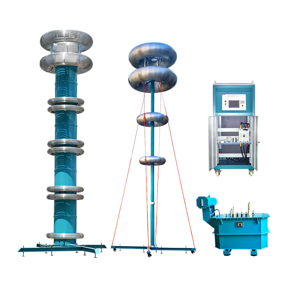
This represents the most significant difference in configuration across the three voltage classes. For 10kV transformers, a 50kV-class power-frequency withstand voltage test system may be configured based on specific test requirements; for 20kV transformers, 75kV-class equipment should be considered; and for 35kV transformers, a 100kV-class system—or one meeting even higher test requirements—is typically necessary. Additionally, the setup should include appropriate high-voltage measuring voltage dividers, current-limiting protective resistors, and overvoltage protection systems. The rated capacity of the test transformer must be sufficient to handle the capacitive current of the test object over the specified test duration; selection should not be based solely on the output voltage.
③. Induced Withstand Voltage and Partial Discharge Testing
A variable-frequency induced withstand voltage test system can be used for all three voltage classes, provided that the output voltage, frequency, waveform, and capacity meet the requirements of the test object. For 35kV transformers, particular attention should be paid to measuring the induced voltage at the high-voltage terminal, ensuring sufficient test power supply capacity, and maintaining proper insulation coordination for high-voltage connections. If the test object is a dry-type transformer, a partial discharge measurement system—compliant with GB/T 1094.11-2022—must also be configured; this includes a low-partial-discharge test power supply, coupling capacitors, measuring impedance, and anti-interference equipment.
④. Turns Ratio, DC Resistance, and Control Systems
These types of equipment generally do not need to be replaced entirely when switching between voltage classes. The turns ratio tester should cover the voltage ratios for all tap positions of the transformer under test, while the DC resistance tester should have a test current selected based on the winding resistance range, inductance, and allowable test duration. For production lines that handle multiple voltage classes, a centralized control system—using a PLC or an industrial PC—is recommended. This can facilitate the automatic switching of test parameters, data acquisition, report generation, and high-voltage safety interlocking, thereby improving testing efficiency.
3. How to Make a Selection for Procurement?
① For primarily testing 10kV transformers:
A standard integrated test bench is a suitable choice, with a focus on cost-effectiveness, coverage of common capacity ranges, and measurement accuracy.
② Testing 10kV and 20kV transformers:
A multi-range configuration is recommended, with high-voltage withstand test equipment rated for the 20kV level, while incorporating expansion interfaces for future upgrades.
③ Testing 10kV, 20kV, and 35kV transformers:
The high-voltage system should be designed based on the insulation test requirements for the 35kV level. Additionally, the ratings for the voltage regulator, test power supply, and instrument transformers must be calculated by considering the maximum capacity requirements across all three voltage classes.
4. Summary
The core differences between comprehensive test benches for 10kV, 20kV, and 35kV transformers lie not in the number of testing functions, but in the test voltage, output capacity, measurement range, and insulation safety specifications. When selecting equipment, the highest voltage level should be determined first; subsequently, individual functional modules—such as the voltage regulator, power supply, and measurement components—should be configured based on the maximum transformer capacity, the required measurement ranges, and the specific test items. This approach prevents insufficient equipment capacity while avoiding unnecessary expenditure, ultimately providing a stable and reliable comprehensive testing platform for transformers of various specifications.
Related Products
Latest News
-
 2026-10-30How to Choose the Right Transformer Comprehensive Test Bench?
-
 2026-10-30What factors affect the accuracy of transformer test results?
-
 2026-10-30What is the basic principle of partial discharge testing?
-
 2026-10-28Compact Portable Transformer Tester for Field Testing
-
 2026-10-28Intelligent CT Tester for Accurate Current Transformer Testing