
Home » News » Company News
CT PT Analyzer for Commissioning: Substation Testing Guide
Instrument-transformer commissioning creates an important bridge between primary equipment and the protection, metering, automation, and monitoring systems that depend on accurate secondary signals. Before energization, the team needs a documented process for identifying each CT or PT, checking the relevant circuits, completing approved tests, resolving exceptions, and handing over reliable records.
A CT PT Analyzer can support this process by consolidating selected instrument-transformer tests. It should be used within an approved project method statement, isolation plan, and safety procedure.
Prepare the Test Package
Commissioning quality depends heavily on preparation. Before entering the test area, review the single-line diagram, wiring drawings, terminal diagrams, protection design, meter configuration, equipment nameplates, and approved test schedule.
- Substation, bay, feeder, transformer, or bus section
- Equipment manufacturer, model, serial number, and location
- CT/PT/VT/CVT/CCVT type
- Core or winding designation
- Primary and secondary ratings
- Ratio and selected tap
- Accuracy class and rated burden
- Rated frequency
- Required standard and acceptance criteria
- Test instrument model and calibration status
- Planned test sequence and responsible personnel
This preparation reduces the risk of testing the wrong core, applying the wrong parameter setting, or recording results against the wrong asset reference.
Establish Safe Test Conditions
Testing must be completed by qualified personnel under approved isolation, grounding, discharge, and work-permit procedures. The test instrument is not a substitute for electrical isolation.
- Confirm the equipment is de-energized and in the required safe state.
- Verify the approved switching and lockout/tagout process.
- Apply grounding as required by the equipment, test method, and site procedure.
- Inspect test leads, terminals, and protective earth conductors.
- Confirm the selected CT core or PT/VT/CVT winding.
- Keep non-test personnel outside the controlled work area.
- Do not connect or remove leads while a test output is active.
For CT testing, particular care is required around secondary circuits. An energized CT secondary must not be left open. For PT, VT, CVT, and CCVT work, the required disconnection and discharge steps should follow the approved drawing and the analyzer wiring instruction for the specific asset.
Commission CTs by Core
Each CT core should be treated as a separate test object. A transformer differential core, feeder protection core, busbar protection core, revenue-metering core, and check-metering core may have different ratios, burdens, accuracy classes, and acceptance requirements.
For CT commissioning, the test plan may require:
- Ratio and turns-ratio verification
- Polarity verification
- Secondary winding resistance
- Excitation characteristics
- Knee-point voltage and current
- Actual secondary burden and impedance
- Ratio error and phase displacement
- 5% or 10% error-curve data where applicable
- ALF, FS, remanence, and transient performance testing results for applicable CT classes
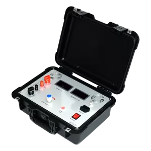
The CTA-1000C CT/PT Analyzer supports CT ratio, polarity, secondary resistance, excitation characteristics, burden, ratio error, and phase displacement, as well as relevant calculated CT results according to the selected class and parameter configuration. Its CT ratio range is 1–40,000, secondary resistance range is 0–300 Ω, and AC burden range is 0–1000 VA.
The test result must be reviewed against the CT nameplate, protection or metering design, installed secondary circuit, selected tap, and project acceptance requirements.
Commission PT, VT, CVT and CCVT Assets
Voltage-transformer assets require their own sequence because the transformer type and test connection can differ significantly.
- Electromagnetic VT or PT
- Capacitive voltage transformer
- Capacitor-coupled voltage transformer
- A unit with separate metering and protection windings
The PTA-2000C VT/CVT Analyzer supports VT, CVT, and CCVT testing for ratio, phase-angle error, secondary winding resistance, excitation characteristics, burden, and error analysis. Its stated VT/CVT coverage extends from 6 kV to 800 kV applications, depending on transformer type and ratio range.
For CVT/CCVT testing, the approved method may include ratio, induction-ratio, resistance, excitation, error, and burden stages. The connection sequence must follow the analyzer prompt, wiring diagram, equipment documentation, and site isolation procedure.
PTA-2000C supports standard settings that include IEC 61869-3 for VT, IEC 61869-5 for CVT/CCVT, IEEE C57.13 for traditional voltage transformers, and ANSI C93.1 for CVT/CCVT applications.
Treat Exceptions as Engineering Findings
A commissioning result should lead to a controlled review, not an immediate wiring change.
A ratio mismatch may result from the selected tap, entered nameplate values, terminal identification, connection method, or an actual equipment issue. An incorrect polarity result requires review of P1/P2 and S1/S2 markings, terminal schedules, protection drawings, relay input direction, and cable identification.
An abnormal excitation curve may require confirmation of the selected core, lead connection, residual magnetism condition, CT class, and manufacturer reference information. A high secondary burden should be assessed by reviewing cable length, conductor size, relay inputs, terminal blocks, meters, test switches, and other connected devices.
For PT, VT, CVT, and CCVT results, review transformer type, selected standard, winding selection, burden, voltage factor, test leads, and approved auxiliary-circuit disconnections before reaching a final conclusion.
Complete the Handover Record
A commissioning report should be traceable and useful after the project enters service. It should include:
- Asset identification and location
- CT core or PT/VT/CVT winding reference
- Nameplate information
- Test date, technician, and environmental conditions
- Instrument model and identification
- Test connection reference
- Selected standard and criteria
- Ratio, polarity, resistance, excitation, burden, and error results as required
- Abnormal findings and corrective actions
- Retest results
- Final engineering disposition
Kvtester supplies CT/PT analyzers and VT/CVT analyzers for substation commissioning, factory inspection, and maintenance work. The appropriate arrangement depends on the instrument-transformer assets, required standard setting, test scope, record-management process, and site conditions.
A repeatable CT/PT commissioning workflow helps identify defects, connection errors, unsuitable burdens, or configuration differences while corrections remain possible. It also creates the evidence required for protection validation, meter setup, final acceptance, and future maintenance.
Related Products





Latest News
-
 2026-09-20ANSI Standard CT Tester: Specs, Tests & Buying Guide
 -
 2026-09-18Why does the required capacity of series resonant test equipment usually increase with cable length?
 -
 2026-09-18How should 35kV cable series resonant withstand voltage test equipment be configured?
 -
 2026-09-18How to Select AC Withstand Voltage Test Equipment for 10kV Cables?
 -
 2026-09-18What parameters must be provided to the manufacturer when purchasing series resonant withstand voltage test equipment?
