
Home » News » Company News
How to Use a CT Tester for Reliable Maintenance Field Testing?
Current transformer maintenance testing is not simply a routine measurement task. It is a practical way to confirm that the CT, its secondary circuit, and the connected protection or metering application can continue to operate as intended.
For maintenance teams, relay engineers, and switchgear service providers, a structured CT testing procedure helps identify wiring mistakes, incorrect ratios, excessive burden, polarity errors, and excitation-related issues before they affect protection performance or metering accuracy. Kvtester power test equipment supports field and factory applications with CT/PT analyzers, relay test systems, transformer test benches, and high-voltage test equipment.
This guide explains how to use a CT tester for maintenance field testing, what to test, how to prepare the CT circuit, and how to interpret the results in a practical maintenance workflow.
Safety notice: Current transformer testing must be performed only by qualified personnel under approved site procedures. Isolation, grounding, CT secondary circuit handling, protective-device bypassing, and restoration must follow the facility’s work permit, lockout/tagout, and protection-control procedures. Never leave the secondary circuit of an energized CT open.
Why CT Maintenance Testing Matters
A current transformer converts high primary current into a standardized secondary current for protection relays, energy meters, measuring instruments, and monitoring systems. If a CT ratio, polarity, burden, or excitation characteristic is incorrect, the issue may affect relay sensitivity, directional protection logic, differential protection stability, or revenue-metering accuracy.
A practical CT maintenance program is commonly used during scheduled preventive maintenance; before commissioning or return to service after installation, overhaul, or replacement; after secondary wiring, relay, meter, or panel modifications; during protection-system troubleshooting; and after fault events or suspected CT saturation issues.
For this work, a portable analyzer should do more than measure one parameter. It should help maintenance personnel assess CT ratio, phase angle, winding resistance, excitation characteristics, polarity, burden impedance, saturation behavior, and key protection-related values from the CT secondary side.
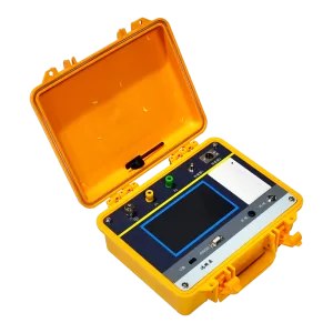
The CTA-1000C CT/PT Analyzer is designed for on-site testing and calibration of metering and protection CTs. It supports CT ratio and phase-angle accuracy, excitation and saturation testing, winding resistance, burden impedance, polarity, inductance, remanence, ALF, and FS evaluation.
What Should Be Tested During CT Maintenance?
The exact test scope depends on the CT type, protection scheme, project requirements, and maintenance history. A complete field-testing procedure commonly includes visual inspection, secondary winding resistance, CT ratio, polarity, excitation characteristics, knee-point performance, secondary burden, ratio error, and phase displacement.
Visual inspection helps identify loose terminals, damaged insulation, corrosion, grounding concerns, and labeling errors. Secondary resistance testing helps assess winding and connection condition. Ratio and polarity tests confirm that the CT is correctly matched to the application. Excitation and knee-point tests help evaluate saturation behavior, while burden testing verifies whether the connected secondary load remains suitable for the CT rating.
The CTA-1000C can perform CT tests for secondary resistance, excitation, ratio, polarity, burden, ratio error, and phase displacement. It can also calculate or display values including knee-point voltage and current, remanence coefficient, saturated and unsaturated inductance, ALF, and instrument security factor.
Step 1: Review the CT Nameplate and Test Scope
Before making any test connection, review the CT nameplate and approved drawings for the installation. This prevents many field-testing errors, especially when a CT has multiple secondary cores, multiple ratios, protection and metering windings, or different terminal arrangements.
Record the CT identification number and installation location, manufacturer, model, serial number, rated primary and secondary current, rated frequency, accuracy class, rated burden, power factor, number of cores, secondary windings, tap positions, selected ratio, and the protection or metering application for each winding. Also record the applicable project specification and previous test values when available.
For protection CTs, additional information may include ALF, knee-point voltage, excitation current, rated symmetrical short-circuit current factor, primary time constant, secondary time constant, or transient performance class.
Do not assume that all CTs require the same parameter settings. A metering CT, a standard protection CT, and a PX, PR, TPX, TPY, TPS, or TPZ class CT may require different input data and different result interpretation.
Step 2: Isolate the CT and Establish a Safe Test Condition
Safe preparation is the foundation of a reliable CT testing procedure. Incorrect isolation or restoration can create unnecessary risk to personnel and equipment.
- Obtain the required work permit and follow approved lockout/tagout procedures.
- Confirm the equipment status and identify the exact CT core and secondary circuit to be tested.
- Verify that the selected CT winding is not supporting an energized or active protection, metering, control, or monitoring function unless the approved procedure specifically allows it.
- Follow the approved procedure for isolating or bypassing affected protection devices.
- Confirm the CT primary circuit condition and approved grounding arrangement.
- Check all secondary terminals, shorting links, test blocks, and terminal markings.
- Record the original wiring and switch position before disconnection.
- Ensure all required connections can be correctly restored after testing.
The CTA-1000C manual requires reliable grounding of the instrument before testing. It also advises users not to connect or disconnect test leads during a test and to avoid exposed circuits or live metal parts. For CT testing, other windings on the same CT should be open, and the CT primary side and equipment should be grounded according to the required test connection.
Step 3: Connect the CT Tester Correctly
Correct connection is essential for meaningful ratio, polarity, resistance, and excitation results. A test result is only as reliable as the selected CT winding, test parameters, and physical wiring.
For a typical CT analyzer connection, output terminals apply a controlled test signal to the CT secondary winding. Secondary measurement terminals measure the CT secondary voltage, while primary or induced-voltage measurement terminals support ratio and polarity testing when required.
For resistance, excitation, and ratio testing, the CTA-1000C uses a four-terminal measurement method. This separates the current-output path from the voltage-measurement path and reduces the influence of test-lead resistance on the final resistance value.
Confirm that the selected secondary winding is correct, S1 and S2 terminal identification is accurate, P1 and P2 direction is understood from the drawing and nameplate, test leads are secure, other CT windings are handled according to the approved procedure, and the instrument is grounded. Do not connect or remove leads while the tester is actively running.
Step 4: Enter the Correct CT Parameters
A CT analyzer can calculate and evaluate many values automatically, but only if the nameplate data and selected CT class are entered correctly.
Typical input parameters include rated primary current, rated secondary current, CT class, rated frequency, rated burden, burden power factor, test temperature, accuracy limit factor, instrument security factor, rated knee-point voltage, excitation current, short-circuit current factor, time constants, and duty cycle where applicable.
The CTA-1000C supports CT classes including P, TPY, metering, PR, PX, TPS, TPX, and TPZ. Its parameter menu allows users to enter rated burden, power factor, ALF, FS, short-circuit current coefficient, time constants, duty cycle, knee-point voltage, and related values when applicable.
A common maintenance error is to test the correct CT but select the wrong class, burden, or ratio. This may not prevent the instrument from producing a result, but it can lead to an incorrect evaluation of ALF, FS, error performance, or transient capability.
Step 5: Perform the Secondary Winding Resistance Test
The secondary winding resistance test checks the electrical condition of the selected CT secondary winding. It is often one of the first electrical tests performed because it can reveal loose terminals, poor contact, damaged wiring, incorrect tap selection, or abnormal winding condition.
- Confirm that the CT is isolated and correctly connected to the tester.
- Select the secondary winding resistance test.
- Enter the current or ambient temperature if the instrument uses temperature compensation.
- Start the test according to the instrument instructions.
- Record the measured resistance and the reference-temperature resistance where available.
- Compare the result with previous records, manufacturer data, matching CT cores, or project-specific criteria.
The CTA-1000C measures secondary winding resistance from 0 to 300 Ω, with a specified accuracy of 0.2% ± 2 mΩ. It can display resistance at the measured temperature and a converted reference value at 75°C.
A resistance result should not be interpreted in isolation. A higher-than-expected value may be caused by terminal oxidation, loose screws, test-lead contact resistance, secondary cable issues, tap-selection differences, or a possible winding problem. Always confirm the test setup before concluding that the CT itself is defective.
Step 6: Perform the CT Ratio Test
The CT ratio test verifies whether the actual transformation ratio matches the nameplate ratio and selected tap. This is especially important after CT replacement, wiring changes, panel modifications, or protection upgrades.
- Confirm the selected CT core and tap.
- Enter the rated primary and secondary current values.
- Select the ratio and polarity test function.
- Confirm the correct connection to the CT secondary and primary measurement terminals.
- Run the test.
- Record actual ratio, turns ratio, ratio error, and phase displacement if available.
- Compare results with the nameplate, design drawings, and applicable acceptance criteria.
The CTA-1000C has a CT ratio test range of 1 to 40,000 with a stated accuracy of ±0.05%. It can provide actual ratio, turns ratio, ratio difference, phase difference, and polarity results.
If the measured ratio does not match the expected value, first check the selected tap, entered nameplate data, test-lead connection, terminal identification, and winding selection. A ratio discrepancy may be caused by a setup issue rather than a CT defect.
Step 7: Verify CT Polarity
CT polarity confirms the relationship between the primary and secondary winding directions. It is critical for applications where current direction matters, including differential protection, directional overcurrent protection, busbar protection, transformer protection, and energy measurement systems.
A polarity error can cause incorrect differential current calculation, unwanted relay operation, failure to operate, incorrect directional element performance, metering errors, or conflicting current-vector relationships in multi-CT protection schemes.
During the polarity test, confirm that the instrument connection matches the intended P1/P2 and S1/S2 terminal orientation. The result should then be checked against the approved schematic, not just the physical label on a field cable.
The CTA-1000C reports CT polarity as positive or negative and supports ratio, polarity, ratio error, and phase-displacement testing within its CT test functions.
Step 8: Test Excitation Characteristics and Knee-Point Performance
Excitation testing evaluates the relationship between applied voltage and magnetizing current. For protection CTs, this test is particularly valuable because it helps assess saturation behavior and determine whether the CT can support the required protection duty.
The excitation curve can provide information on knee-point voltage and current, core saturation behavior, magnetizing current, unsaturated inductance, saturated inductance, and residual magnetism.
For the CTA-1000C, the knee point is determined using the criterion that a 10% increase in voltage produces a 50% increase in excitation current.
- Select the correct CT class and enter the required nameplate values.
- Confirm that the correct secondary winding is connected.
- Select the excitation test function.
- Start the automated test.
- Save the excitation curve and test data.
- Record knee-point voltage, knee-point current, excitation current, inductance values, and remanence information where applicable.
- Compare the curve and calculated values with the CT data sheet, protection design requirement, project specification, and historical test records.
Do not use one generic knee-point value as an acceptance criterion for every protection CT. The correct evaluation depends on CT class, protection application, burden, relay requirements, fault current, and system duty.
Step 9: Measure the CT Secondary Burden
The CT burden test determines the load connected to the CT secondary circuit. The connected burden can include relay inputs, meters, transducers, cable resistance, terminal blocks, test switches, and related secondary-circuit components.
An excessive burden can reduce accuracy and may increase the likelihood of CT saturation under fault conditions. A burden test is especially important after secondary wiring changes, relay replacements, panel extensions, or additional metering equipment installation.
- Verify the CT secondary circuit configuration.
- Select the burden test function.
- Connect the tester according to the approved burden-test wiring method.
- Measure actual burden in VA, impedance, and power factor where available.
- Compare the result with the CT nameplate burden and the protection or metering design requirement.
- Record the connected equipment and circuit condition at the time of testing.
The CTA-1000C supports AC burden testing from 0 to 1,000 VA, with an accuracy specification of 0.2% ± 0.02 VA. It can display actual load, power factor, and secondary impedance.
Step 10: Review ALF, FS, Ratio Error, and Phase Displacement
For protection and metering CTs, the basic pass/fail question often extends beyond ratio alone.
For protection CTs, maintenance teams may need to review excitation behavior, knee-point voltage, ALF, composite error, saturation characteristics, burden impedance, remanence coefficient, and transient-related parameters for TP-class CTs.
For metering CTs, maintenance teams may focus on ratio accuracy, phase displacement, connected burden, instrument security factor, winding resistance, polarity, and performance at the actual operating burden.
The CTA-1000C can calculate values such as actual ALF, actual instrument security factor, ratio difference, phase difference, limiting electromotive force, remanence coefficient, and related CT performance data according to the selected test configuration.
The correct interpretation should always be based on the CT nameplate, selected accuracy class, applicable project requirements, selected IEC or IEEE evaluation standard, and historical trend data. Avoid applying a universal acceptance limit across all CT designs and protection applications.
Common CT Field Testing Problems
If the ratio does not match the nameplate, confirm the selected tap, rated-current entries, terminal selection, and tester connection before diagnosing a CT fault. If polarity is incorrect, check P1/P2 and S1/S2 orientation, the approved secondary schematic, and the field cable labeling.
If secondary resistance is higher than expected, inspect test-lead contact, terminal tightness, oxidation, temperature correction, and selected tap. If the excitation curve appears abnormal, confirm the CT class settings, selected secondary core, test connections, and comparison baseline. Residual magnetism or an incorrect test configuration may affect interpretation.
If burden exceeds the expected value, check connected relay and meter inputs, cable length, wire resistance, terminal conditions, and any secondary-circuit changes. If test results are unstable, inspect the test leads, grounding, surrounding interference, instrument settings, and connection security.
When to Use an Advanced CT/PT Analyzer
Routine maintenance often requires a portable instrument that can test multiple CT characteristics without repeatedly changing test equipment. This is especially useful for service teams working across multiple bays, switchgear lineups, substations, or protection panels.
For higher ratio-accuracy requirements, the CTA-1000D CT/PT Analyzer supports CT ratio, phase angle, winding resistance, excitation, burden, polarity, saturation, inductance, remanence, ALF, and FS testing functions. Its specified CT ratio accuracy is 0.02% in the applicable lower ratio range, and the unit is designed for portable field testing.
When selecting a CT tester for maintenance, consider the required CT classes, ratio and phase-angle accuracy, need for excitation and knee-point testing, need for burden and protection-parameter evaluation, applicable standards, portability, connection accessories, and report-management requirements.
CT Test Report and Restoration Checklist
A high-quality CT maintenance report should make the work repeatable and traceable. Record the project and equipment identification, CT manufacturer and nameplate data, tested core and winding, test date, environmental conditions, technician, test instrument model and serial number, test connections, resistance results, ratio and polarity results, excitation curve, knee-point values, burden result, calculated parameters, comparison basis, and any corrective actions.
Before the work is closed, confirm that the secondary circuit, protection functions, grounds, terminals, shorting links, test switches, and related equipment have been restored according to the approved procedure. Complete the required independent check or handover process before returning equipment to service.
Reliable CT Testing Starts With the Right Process
A CT tester for maintenance should help your team move from isolated measurements to an informed equipment decision. By combining safe preparation, correct wiring, accurate parameter entry, structured testing, and disciplined result review, maintenance personnel can identify potential CT and secondary-circuit issues before they become protection, metering, or reliability problems.
For on-site CT and PT testing requirements, Kvtester provides portable analyzers and broader power-testing solutions for protection, metering, switchgear, transformer, and substation maintenance applications. Discuss your CT class, testing standard, and field workflow with our technical team to select a suitable testing configuration.
Related Products





Latest News
-
 2026-09-09High Precision Transformer Testing Equipment Price & FAT Guide
 -
 2026-09-09IEC Standard CT Tester Buyer’s Guide for Utilities and Testing Companies
 -
 2026-08-26Proper Usage and Operating Procedures for DC High-Voltage Generators
 -
 2026-08-26How do you choose a DC high-voltage generator?
 -
 2026-08-26What is a DC High-Voltage Generator?
