
Home » News » Company News
How an Intelligent Transformer Tester Supports Safe Transformer Testing
Before a power or distribution transformer leaves a factory, returns to service after repair, or enters a new energy project, the test team needs clear answers: Does the core operate as expected? Are winding losses and impedance within the required range? Can the insulation withstand the specified electrical stress? No-load, load-loss, and withstand tests address these questions in a structured sequence.
This guide explains how no-load, load-loss, applied-voltage withstand, and induced-voltage withstand tests fit together. It is intended for qualified personnel working with power and distribution transformers. The transformer nameplate, approved test plan, applicable standards, and local safety rules determine the final connection method, voltage, frequency, duration, and acceptance criteria.
What Does Each Transformer Test Check?
Each test focuses on a different part of transformer performance. Reviewing the results together helps the test team distinguish possible magnetic-circuit, winding-loss, impedance, and insulation concerns.
No-Load Test
A transformer no-load test measures no-load current and no-load loss while one winding is energized at the specified voltage and frequency and the other winding remains open. The measured loss is mainly associated with the transformer core under excitation. The test record should include the selected tap position, three-phase voltage, current, active power, power factor, frequency, and the applicable test conditions.
Load-Loss and Short-Circuit Impedance Test
In this article, “load test” means a load-loss and short-circuit impedance test, not long-term operation with a customer’s actual load connected. The test uses an approved short-circuit connection and controlled input to bring the test current to the required value. It provides load-loss and impedance-voltage data for manufacturing quality checks, maintenance verification, and parallel-operation assessments.
Applied-Voltage Withstand Test
An applied-voltage, or power-frequency withstand, test checks the insulation arrangement between the energized winding and grounded or non-energized parts as specified by the test procedure. It is a high-voltage test that requires controlled energization, suitable protection, a restricted test area, and continuous monitoring.
Induced-Voltage Withstand Test
An induced-voltage withstand test applies voltage through transformer action to assess winding insulation under the approved test conditions. Because the test may use elevated voltage, the selected frequency and test duration must follow the project specification and the transformer design requirements.
Prepare the Transformer Test Bench Before Energization
Accurate results and safe operation both begin with preparation. Before any test, review the transformer rating plate and test sheet, including rated capacity, voltage ratio, vector group, frequency, tap position, insulation requirements, and the required test sequence.
The test area should be dry, controlled, and clearly separated from non-test personnel. Confirm that the transformer is isolated from external circuits, that test leads are rated for the task, and that every required grounding connection is secure. Do not connect or disconnect test leads while the circuit is energized.
When transformer testing involves several electrical measurements and high-voltage test stages, a coordinated test system can help make the workflow easier to organize. Kvtester supplies electrical test equipment for transformer manufacturers, power utilities, testing organizations, and engineering teams. Its intelligent transformer test systems can combine controlled power supply, measurement, protection, and test-data management, helping qualified operators complete routine transformer verification with clearer operating steps.
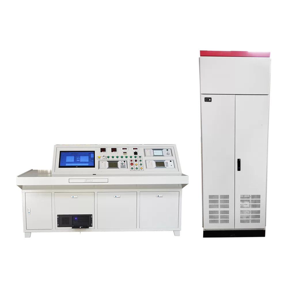
For factory and maintenance workflows that require multiple test functions, the ZC-200 Transformer Test Control Desk combines no-load and load characteristic testing with winding resistance, transformation ratio group, insulation resistance, power-frequency withstand voltage, and induced withstand voltage testing. Its modular arrangement supports separate test functions as well as coordinated computer-based test selection, data collection, and report preparation.
How to Perform a Transformer No-Load Test
The no-load test is normally performed after the test plan, wiring, and measuring ranges have been confirmed. The energized winding and test voltage should follow the approved procedure for the transformer under test.
1.Set Up the No-Load Test Circuit
Connect the specified winding to the controlled AC source and leave the other winding open as required by the test plan. Confirm the phase sequence and select voltage and current measuring ranges that match the transformer rating and expected no-load current. For a tapped transformer, record the tap position before starting the test.
2.Raise Voltage in a Controlled Manner
After the circuit and safety boundary have been checked, close the approved control circuit and raise voltage smoothly from zero. Watch the three-phase voltage and current during the rise. Once the specified test condition is reached, allow the readings to stabilize before recording the results.
3.Record the Data That Matters
Record three-phase voltage, current, active power, power factor, frequency, test duration, tap position, and ambient conditions required by the test procedure. A useful no-load record is more than one total power value; it should show whether the phase readings and operating conditions were stable and consistent.
4.Reduce Voltage and Review the Result
Return the regulator to zero before opening the circuit. Compare the result with the approved technical specification, guaranteed values, previous test records, and the applicable correction method. If no-load current or loss appears unusual, first verify the tap setting, wiring, phase sequence, source voltage, frequency, and meter range before drawing a conclusion about the transformer.
How to Perform a Load-Loss and Short-Circuit Impedance Test
A load-loss test uses a short-circuit arrangement to evaluate transformer losses and impedance under the required current condition. It should be completed with secure shorting links, correct current-range selection, and a test duration that follows the approved work instruction.
1.Build the Approved Short-Circuit Connection
Short the specified winding using conductors and connections suitable for the required current. Supply the other winding through the test bench according to the approved diagram. Check all bolted connections, grounding paths, and current-transformer ranges before applying voltage.
2.Select the Test Range and Increase Current Gradually
Select the voltage and current ranges that suit the transformer capacity and expected test current. Increase voltage gradually from zero until the current reaches the required test value. Do not treat the test as a simple full-load operating test: the objective is controlled measurement of load loss and impedance under the specified short-circuit condition.
3.Capture Stable Load-Loss Data
When readings stabilize, record voltage, current, active power, power factor, frequency, tap position, and winding temperature or the temperature data required for correction. Winding temperature matters because conductor resistance and load-loss results change with temperature.
4.Evaluate Loss and Impedance Correctly
Reduce voltage to zero immediately after the required measurements are complete. Compare corrected results with the transformer’s technical agreement, factory design values, and comparable historical records. A higher-than-expected loss or an impedance deviation should trigger a review of test current, temperature correction, lead connections, tap setting, and transformer manufacturing or repair records rather than an immediate single-cause diagnosis.
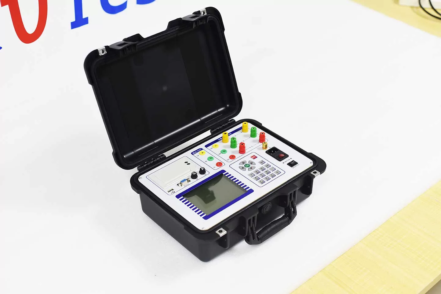
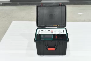
When the task focuses on capacity, no-load current, no-load loss, short-circuit loss, and impedance voltage measurement, the ZC-202B Transformer Capacity and Load Tester supports three-phase no-load and load testing. It displays three-phase voltage and current vectors for wiring verification and applies waveform, temperature, non-rated-voltage, and non-rated-current corrections to test results.
How to Perform an Applied-Voltage Withstand Test
The applied-voltage withstand test evaluates insulation strength, so safety controls are as important as the electrical connection. Qualified personnel should perform the test under an approved procedure.
1.Confirm Test Voltage, Duration, and Grounding Points
Verify the specified test voltage, frequency, duration, protection settings, and grounding arrangement before energization. Confirm which winding is under test, which terminals must be grounded, and which terminals must remain isolated. The high-voltage return end and transformer enclosure must be grounded as required by the connection diagram.
2.Conduct an Empty-Rise Check When Required
Before connecting the transformer, an empty-rise check may be used to verify instrument readings, voltage control, and protection behavior. This helps the test team confirm that the control system and measuring path respond as expected before high voltage is applied to the transformer.
3.Raise Voltage Smoothly and Hold the Required Test Level
Start with the regulator at zero, then raise voltage smoothly while monitoring voltage, current, and transformer condition. When the specified test voltage is reached, begin timing according to the approved procedure. A 60-second power-frequency withstand sequence is a common operating arrangement; the actual voltage and duration must be set by the transformer requirement.
4.Stop Safely if an Abnormal Condition Appears
Immediately reduce voltage and disconnect power if there is abnormal meter movement, smoke, insulation odor, unexpected sound, or another unsafe condition. At the end of a normal test, lower the regulator to zero, disconnect power, complete the required discharge and grounding confirmation, and only then approach the test object or change wiring.
How to Perform an Induced-Voltage Withstand Test
The induced-voltage test requires the test source, frequency, applied voltage, tap position, and duration to be coordinated with the transformer’s approved test requirements. It is not interchangeable with an applied-voltage test.
1.Verify the Frequency-Related Test Setup
Connect the specified transformer winding to the approved test source and keep other terminals in the required condition. Check phase sequence, frequency setting, output condition, grounding, and protective devices before starting. A generator-based arrangement can provide the required frequency and allows the operator to monitor excitation current, output voltage, and output current.
2.Apply Excitation Gradually
Start the approved frequency source and raise excitation gradually from zero. Monitor voltage, current, sound, vibration, and protective indications throughout the test. Use the specified frequency to maintain the intended test condition and avoid operating outside the approved magnetic limits.
3.Hold, Reduce, and Document
When the specified test level is reached, maintain it for the required duration while continuing to monitor the transformer and test bench. At completion, reduce the output to zero in a controlled manner, disconnect according to the safety procedure, and record the test conditions and results. Timed induced-voltage testing with controlled output reduction helps keep the operation consistent from one transformer to the next.
Common Questions During Transformer Testing
Is a no-load test the same as a load test?
No. A no-load test measures excitation-related current and loss with the specified secondary winding open. A load-loss and short-circuit impedance test measures loss and impedance under a controlled short-circuit current condition. The wiring, electrical objective, and interpretation are different.
Can one intelligent test bench complete all transformer tests?
It depends on the bench configuration and transformer rating. A comprehensive system may cover no-load characteristics, load characteristics, winding resistance, transformation ratio group, insulation resistance, power-frequency withstand voltage, and induced withstand voltage. The selected configuration must match transformer capacity, voltage class, required test items, and the project’s test specification.
Why should results be compared with more than one reference?
Test values are affected by tap position, temperature, source conditions, measurement range, and transformer design. Compare results with the applicable technical agreement, approved factory limits, corrected values, and previous records when available. This gives the engineering team a clearer basis for deciding whether to repeat the test, investigate the setup, or review the transformer.
When should a test be stopped?
Stop the test when an unsafe or abnormal condition appears, including abnormal instrument indication, smoke, burning smell, unexpected sound, loss of grounding, or a protection action. Reduce voltage first where safe to do so, disconnect the supply, secure the area, and investigate before restarting.
Build a Repeatable Transformer Test Workflow
A complete transformer test process should make the technical sequence easy to repeat: verify the nameplate and test plan, prepare the circuit, select the correct range, raise voltage or current under control, record stable readings, reduce to zero, and preserve the result with the relevant operating conditions. This workflow supports routine factory testing, post-maintenance quality checks, and project acceptance work when applied by qualified teams.
For broader configuration options covering transformer benches, ratio testing, short-circuit impedance testing, and DC resistance measurement, explore the transformer test equipment range. Selecting equipment by transformer rating, required test items, automation level, and safety requirements helps create a test process that is easier to manage from the first connection through final data review.
Related Products





Latest News
-
 2026-09-17ANSI Standard Six Phase CT Tester Manufacturer: OEM Selection Guide
 -
 2026-09-17
 -
 2026-09-10What causes unstable or fluctuating dielectric loss test data?
 -
 2026-09-10What causes high dielectric loss values? Common causes and troubleshooting approaches
 - 2026-09-10What is the difference between the “normal connection” and “reverse connection” methods for dielectric loss testers?
