1. What Is a CT PT Analyzer?
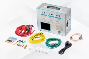
A CT PT analyzer is a professional, integrated testing instrument built to calibrate, diagnose, and verify the performance of current and potential transformers used in power plants, substations, and high-voltage power systems. The all-in-one CT PT analyzer for power plant consolidates multiple standalone testing functions into a single portable or desktop unit. It replaces separate traditional testers used for CT excitation characteristic testing, PT ratio error detection, polarity verification, secondary burden analysis, and winding resistance measurement.
Engineered specifically for power plant operating conditions, this analyzer supports testing for protection-grade, metering-grade, and TP-class CTs, as well as all standard electromagnetic PT models. It automatically calculates critical parameters including ratio error, phase displacement, knee-point voltage, secondary load capacity, and insulation performance. It also generates standardized test reports that comply with IEC 61869 and IEEE C57.13 industry standards. The device supports full-lifecycle CT/PT testing, covering factory pre-delivery inspection, on-site commissioning, routine daily maintenance, and on-site fault diagnosis for power plant infrastructure.
2. What Are CT and PT in a Power System?
CTs and PTs are essential auxiliary components in high-voltage power systems, collectively referred to as instrument transformers. Acting as the “eyes and ears” of power plant operations, they step down extreme grid voltage and current levels into standardized low-level signals for precise measurement, power metering, system protection, and real-time grid monitoring.
Current Transformer (CT)
A Current Transformer (CT) steps down high primary current in power plant circuits to a standardized low secondary current (typically 1A or 5A). It electrically isolates high-voltage main circuits from low-voltage measurement and protection devices, safeguarding both on-site personnel and connected equipment. CTs are widely deployed for current metering, overload protection, and short-circuit fault detection at generator outlets, transmission lines, and substation facilities within power plants.
Potential Transformer (PT / VT)
A Potential Transformer (PT), also commonly known as a Voltage Transformer (VT), reduces high system voltage to a standardized low secondary voltage. This enables accurate voltage monitoring, energy metering, and reliable relay protection across power networks. In power plants, PTs capture precise grid voltage data to support power factor regulation, maintain grid stability, and trigger early fault warning systems.
The accuracy of power plant metering data and the reliability of system protection actions depend entirely on properly functioning CT and PT transformers. Even minor performance deviations can lead to inaccurate energy billing, protection system malfunctions, and severe operational risks for the entire power grid.
3. How Does an All-in-one CT PT Analyzer Work?
The all-in-one CT PT analyzer for power plant operates on high-precision signal sampling, automated parameter calculation, and standard-based data comparison, delivering full-parameter testing through a streamlined, fully automated workflow. Its testing process follows four clear, sequential steps:
Step 1: Parameter Input and Standard Matching
Technicians input CT/PT nameplate specifications, including transformation ratio, rated burden, and accuracy class, then select applicable industry standards such as IEC 61869, GB 1208, and IEEE C57.13. The analyzer automatically matches the optimal testing algorithm and compliance evaluation criteria for the specific device under test.
Step 2: Automatic Signal Excitation and Sampling
The device’s built-in high-precision power module outputs stable excitation signals to the primary side of CT and PT units, while a high-speed sampling system captures real-time current and voltage data from the secondary side. It synchronously collects key operational data, including excitation characteristics, winding resistance, and secondary load parameters.
Step 3: Data Calculation and Error Analysis
The analyzer’s embedded intelligent algorithm automatically calculates critical performance metrics, such as transformation ratio error, phase error, knee-point voltage, excitation current, and secondary burden margin. It compares measured values against standard allowable error thresholds to determine whether the tested CT or PT unit meets operational qualification requirements.
Step 4: Result Output and Report Generation
Once testing is complete, the analyzer displays clear pass/fail results on its LCD screen. It supports on-site data storage, instant printing, and flexible data export, generating fully standardized test reports for power plant equipment archiving, routine inspections, and regulatory audits.
Unlike traditional testing setups that require repetitive manual wiring and time-consuming debugging, this all-in-one analyzer only needs a single wiring setup to complete all test items, drastically simplifying on-site testing operations for power plant teams.
4. Key Advantages of Using an All-in-one CT PT Analyzer for Power Plants
Traditional CT/PT testing for power plants relies on multiple separate devices, complicated wiring layouts, and lengthy testing cycles. The integrated all-in-one CT PT analyzer solves these common operational pain points, delivering significant advantages for power plant maintenance and daily operations:
- Full-Function Integrated Testing: A single unit handles all essential CT and PT tests, including ratio verification, polarity checking, excitation characteristic analysis, secondary burden testing, winding resistance measurement, and error curve plotting. This eliminates the need to purchase, transport, and maintain multiple single-function testers.
- Superior Testing Efficiency: Fully automated testing and one-click report generation cut manual workload by over 60%. The device reduces testing time for a single CT/PT set from several hours to just minutes, making it ideal for large-scale batch testing in commercial power plants.
- High Precision & Full Compliance: Equipped with industry-calibrated algorithms and high-resolution sampling chips, the analyzer fully complies with IEC and IEEE international standards. It guarantees highly accurate test data for power plant metering calibration and protection system validation.
- Portable & Field-Ready Design: Featuring a lightweight build and robust anti-interference performance, the analyzer adapts to harsh electromagnetic environments in power plant workshops and substations, supporting flexible on-site commissioning and emergency fault troubleshooting.
- Smart Data Management: It supports local data storage, historical record query, and remote data export, streamlining full-lifecycle equipment management, routine inspection documentation, and regulatory compliance audits for power plants.
- Excellent Cost Efficiency: By consolidating dozens of testing functions into one device, it lowers equipment procurement costs, reduces routine maintenance expenses, and minimizes labor hours, cutting overall operational costs for power plant electrical testing workflows.
5. Are CT PT Transformers Safe to Use?
CT and PT transformers are inherently safe, reliable pieces of power system equipment when installed, operated, and calibrated per official industry standards. Designed as critical high-voltage isolation components, they pose zero safety risks under standard operating conditions, thanks to purpose-built safety features and standardized operating protocols:
Safety Design Features
Both CT and PT units adopt high-grade high-voltage insulation isolation structures, which completely separate high-voltage primary circuits from low-voltage secondary testing and control loops. This core design protects field technicians and low-voltage auxiliary equipment from high-voltage breakdown hazards. Additionally, built-in overvoltage and overcurrent protection mechanisms shield the transformers from sudden grid surge impacts.
Key Safety Operating Specifications
Virtually all CT/PT safety incidents stem from non-standard operation. The most critical safety rule to follow is: never open the secondary circuit of an energized CT. An open CT secondary loop induces extreme high voltage, which can cause insulation failure and severe personal injury. For PT units, operators must avoid secondary circuit short-circuits to prevent permanent device burnout.
Scheduled routine calibration with a professional all-in-one CT PT analyzer for power plant helps detect early signs of insulation degradation, ratio drift, and latent equipment faults, ensuring long-term, stable, and safe operation of CT and PT transformer systems.
6. What Is the Output Voltage of a PT?
Potential Transformers (PTs) follow unified industry-standard secondary output voltage specifications to ensure full compatibility with standard power system measuring instruments and protection devices. Standard PT output voltages vary based on system voltage class, as outlined below:
- High-voltage power plant PT (35kV/110kV/220kV systems): Delivers a standard secondary line voltage output of 100V, the most widely adopted specification for power plant substations worldwide.
- Low-voltage system PT: Certain low-voltage PT models provide a 100/√3V phase voltage output to accommodate specialized grid measurement requirements.
The standardized 100V secondary output unifies signal parameters for global power system measurement and protection infrastructure. The all-in-one CT PT analyzer precisely calibrates PT output voltage accuracy, ensuring all errors fall within officially permitted ranges. This prevents inaccurate energy metering and unintended protection system trips caused by voltage output deviations.
7. CT PT Transformer vs Power Transformer: Core Differences
It is common for industry newcomers to confuse CT/PT instrument transformers with standard power transformers. However, the two devices serve entirely distinct purposes, with fundamental differences in operational function, physical structure, working conditions, and performance criteria, as summarized in the table below:
Comparison Dimension | CT/PT Transformer (Instrument Transformer) | Power Transformer |
Core Function | Precision signal conversion for metering, measurement, and system protection; no bulk power transmission capability | Voltage level step-up/step-down for large-scale grid power transmission and distribution |
Working Load | Operates continuously under light or no-load conditions with minimal secondary burden | Runs long-term at full or heavy load to handle bulk power throughput |
Performance Requirement | Ultra-high accuracy grades (0.2/0.5/1.0) with strict tolerance limits for minimal signal error | Prioritizes transmission efficiency and insulation stability; relaxed accuracy tolerances |
Structure & Volume | Compact, lightweight, and structurally simple | Large, heavy-duty build with complex cooling and insulation structures |
Testing Focus | Ratio error, phase error, polarity verification, and excitation characteristic testing via dedicated CT PT analyzers | Insulation resistance, winding loss, transformation ratio consistency, and load loss testing |
8. How Much Do CT PT Transformers Cost?
The market cost of power plant CT and PT transformers varies significantly based on voltage rating, accuracy class, transformer type (electromagnetic, GIS, or combined), and application scenario. Below are the 2026 mainstream market price ranges for industrial and utility-grade units:
CT Transformer Price Range
- Low-voltage CT (0.4kV): $20 – $150 (standard metering-grade for general applications)
- Medium-voltage CT (10kV/35kV): $150 – $800 (dual-purpose for protection and metering)
- High-voltage CT (110kV/220kV): $800 – $3,500 (TP-class premium units designed exclusively for power plants)
PT Transformer Price Range
- Medium-voltage PT (10kV/35kV): $200 – $900
- High-voltage PT (110kV/220kV): $900 – $4,000
Cost Influencing Factors
Premium protection-grade and TP-class CT/PT units for large-scale power plants command higher prices due to stringent manufacturing tolerances and enhanced performance standards. GIS-type and integrated box-style transformers also cost more than conventional electromagnetic models. Regular professional calibration using an all-in-one CT PT analyzer for power plant extends the service lifespan of CT/PT transformers substantially, reducing long-term replacement and maintenance expenses for power facilities.
Final Thoughts
CT and PT transformers form the foundational infrastructure for safe, accurate, and efficient power plant operation, while a reliable all-in-one CT PT analyzer for power plant is the essential tool to sustain their optimal performance. It unifies high-efficiency field testing, precise data analytics, and standardized compliance validation, empowering power plant teams to streamline equipment commissioning, routine maintenance, and fault troubleshooting workflows. A solid understanding of CT/PT operating principles, safety protocols, and cost factors helps power enterprises refine their maintenance strategies, mitigate operational hazards, and boost overall power system efficiency.






 2026-09-302026 Top 3 Chinese Insulation Resistance Transformer Testing Equipment Manufacturers
 2026-09-30Industrial CT Tester: How Is It Used for Current Transformer Factory Testing?
 2026-09-30How Can a CT PT Analyzer Improve CT and PT Quality Testing in the Laboratory?
 2026-09-30How to Perform Current Transformer Testing Step by Step?
 2026-09-30How to Perform CT Analyzer Testing and Evaluate the Test Results?