
Home » News » Company News
Smart CT/PT Analyzer Results: How to Read Ratio, Phase and Polarity
A CT/PT analyzer does more than display a pass/fail message. It provides measurement data that helps engineers confirm whether an instrument transformer is correctly connected, accurately converting current or voltage, and suitable for its intended metering or protection duty.
Whether you are commissioning a substation, performing preventive maintenance, inspecting transformer production quality, or troubleshooting a protection circuit, three results deserve close attention: ratio error, phase displacement, and polarity. Understanding these values in their testing context helps you avoid incorrect conclusions and identify issues before energization.
KVtester provides CT, PT, VT, CVT, transformer, relay protection, and high-voltage testing equipment for field maintenance, manufacturing inspection, and laboratory applications. Its CT/PT product range includes a universal CT/PT analyzer and a dedicated VT/CVT analyzer for more specialized voltage-transformer testing tasks.
Read the Test Context First
Before interpreting any number on the screen, verify that the analyzer was configured with the correct transformer and test conditions. A precise result is only meaningful when the input data and wiring are correct.
Confirm the following items before making a pass/fail decision:
- Transformer type: CT, electromagnetic PT/VT, or CVT
- Application: metering, protection, or transient protection
- Rated primary and secondary current or voltage
- Rated transformation ratio
- Accuracy class, such as 0.2S, 0.5, 5P20, PX, TPX, TPY, or TPZ
- Rated burden, actual burden, and burden power factor
- Rated frequency: 50 Hz or 60 Hz
- Applicable project specification and standard, such as IEC 61869-1 and IEC 61869-2
For a CT, a result measured at 5% of rated current may differ from the result measured at 100% or 120% of rated current. Similarly, changing the burden from 1.25 VA to 5 VA, or changing the burden power factor, can change ratio error and phase displacement. Therefore, never assess a result by looking at only one number without checking the corresponding current point and burden condition.
For protection CTs, ratio error and phase displacement are important, but they are not the full evaluation. Excitation characteristics, knee-point voltage, secondary winding resistance, actual burden, accuracy limit factor, and transient performance may also be required. For metering CTs, ratio error and phase displacement usually have more direct influence on measurement accuracy.
| Display field | What it means |
| Ratio | The measured actual transformation ratio |
| Turns Ratio | The measured winding-turn relationship |
| Ratio Error | The percentage difference between actual and rated transformation performance |
| Phase Displacement | The phase-angle difference between primary and secondary quantities |
| Polarity | Whether the primary and secondary terminal relationship matches the expected direction |
| I/Ipn (%) | Test current expressed as a percentage of rated primary current |
| VA/PF | Burden value and burden power factor |
| Resistance | Secondary winding resistance, often corrected to a reference temperature |
| Excitation / Knee Point | Magnetic performance information, particularly relevant to protection CTs |
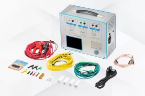
The CTA-1000C CT/PT Analyzer is designed for both CT and PT testing. It supports ratio, polarity, ratio error, phase displacement, excitation, secondary winding resistance, and burden-related measurements, allowing users to interpret accuracy data alongside the transformer’s wider electrical condition. Its CT and PT ratio test range is 1 to 40,000, while its CT ratio accuracy is listed as ±0.05%.
How to Interpret Ratio Error
Ratio error tells you how closely the actual transformation behavior matches the rated ratio under the selected test condition.
For example, a CT with a rated ratio of 1000/5 A has a nominal ratio of 200:1. In an ideal condition, 1000 A on the primary side corresponds to 5 A on the secondary side. In real operation, the CT requires excitation current to magnetize its core. This means the secondary current, when referred to the primary side, may not precisely match the primary current. That difference creates ratio error.
Ratio Error = ((K(n) × I(s)) − I(p)) / I(p) × 100%
Where K(n) is the rated transformation ratio, I(s) is the secondary current, and I(p) is the primary current.
The exact formula and sign convention used in a test report should follow the applicable standard and the analyzer’s calculation method. Do not assume that a positive or negative value automatically means “good” or “bad.” The key question is whether the measured result remains within the permitted tolerance for the transformer’s class, current point, burden, and power factor.
Example: Reading a Ratio Result
| Parameter | Example result |
| Rated ratio | 1000/5 A |
| Accuracy class | 0.5 |
| Test current | 100% of rated current |
| Burden | 5 VA / PF 0.8 |
| Ratio error | −0.08% |
| Phase displacement | +2.5 min |
| Polarity | OK |
This result cannot be judged from the −0.08% value alone. The technician must compare it with the accuracy limits applicable to the stated CT class, the selected burden, and the relevant standard or project requirement. If the CT is a metering transformer, both ratio error and phase displacement must be checked. If it is a protection CT, additional protection-specific parameters must also be reviewed.
Common Causes of Excessive Ratio Error
If ratio error is larger than expected, check these items in order:
- Incorrect rated ratio entered into the analyzer
- Wrong CT tap or secondary terminal selected
- Incorrect primary or secondary lead connection
- Burden above the CT nameplate rating
- Loose terminal connection or excessive secondary circuit resistance
- Wrong burden power-factor setting
- Secondary winding damage or abnormal resistance
- Core saturation, residual magnetism, or excitation-curve abnormality
- Testing at a current point not applicable to the required accuracy class
A ratio error that appears only at high current may indicate saturation-related behavior or burden issues. A large error at all current points may point to a wrong tap selection, wiring error, incorrect nameplate entry, or a more serious winding/core problem.
How to Interpret Phase Displacement
Phase displacement, also called phase-angle error, is the angular difference between the primary quantity and the secondary quantity after accounting for the rated transformation ratio.
It is commonly displayed in angular minutes, written as min or ′. In this context, min means arcminutes, not time in minutes.
For metering CTs, phase displacement matters because electrical energy meters calculate active power, reactive power, apparent power, and power factor from voltage-current relationships. Even if a CT has acceptable ratio error, excessive phase displacement can still introduce metering error, especially where power factor is low.
For PTs and VTs, phase displacement can affect voltage-based measurement and protection calculations. In systems using several CTs and PTs together, small angular errors may accumulate in sensitive metering or protection applications.
| Item | Ratio Error | Phase Displacement |
| Main purpose | Evaluates magnitude conversion accuracy | Evaluates angular conversion accuracy |
| Typical unit | Percentage (%) | Arcminutes (min or ′) |
| Primary impact | Current/voltage magnitude measurement | Power, energy, power factor, vector calculation |
| Influenced by | Burden, excitation current, resistance, saturation | Burden, power factor, magnetic characteristics, wiring direction |
| Must be checked for metering CTs | Yes | Yes |
| Enough by itself for protection CT evaluation | No | No |
The sign of phase displacement must be interpreted according to the analyzer’s vector convention, selected terminals, and applicable standard. A positive phase displacement on one instrument may use a different reference direction from another instrument. Your report should state the test method and terminal relationship rather than relying on a sign alone.
Why Phase Displacement Can Change
Phase displacement may become abnormal because of:
- Incorrect polarity or terminal connection
- Incorrect burden power factor entered during testing
- Burden outside the CT’s rated operating condition
- High secondary loop resistance
- Core magnetic nonlinearity
- Residual magnetism after fault current or DC influence
- Harmonic-rich operating environments
- Saturation under high current or unsuitable burden conditions
If ratio error is acceptable but phase displacement fails, do not dismiss the result. Recheck the burden/PF settings and wiring first, then repeat the test at the specified current points. If the condition persists, review excitation data and verify whether the transformer is being assessed according to the correct metering or protection requirement.
How to Read Polarity Results
Polarity indicates the directional relationship between the primary and secondary terminals of a CT or PT.
For CTs, terminals are commonly marked as P1/P2 on the primary side and S1/S2 on the secondary side. When current enters P1, the corresponding secondary current direction should align with the expected terminal convention at S1. This relationship is essential when CTs are connected in differential protection, busbar protection, transformer protection, parallel metering circuits, and other directional applications.
An analyzer may show results such as Polarity: OK, Positive, Negative, Reverse, or Fail. The wording differs by instrument. In practice, Polarity: OK generally means the measured terminal relationship matches the connection and reference direction expected by the analyzer. It does not eliminate the need to verify that the physical field wiring matches the protection drawing and terminal schedule.
Why a Polarity Error Matters
A reversed CT can create serious operational problems:
- Differential protection may see through-current as internal fault current
- Transformer differential schemes may produce false differential current
- Parallel CT circuits may oppose each other
- Metering direction may be incorrect
- Power and energy records may be inaccurate
- Directional protection calculations may become unreliable
If the polarity result is abnormal, stop and verify the following before retesting:
- Confirm the CT nameplate terminal markings.
- Check the primary conductor direction through the CT.
- Verify the S1/S2 wiring at the secondary terminal block.
- Compare field connections with approved drawings.
- Confirm that the analyzer leads are connected to the intended terminals.
- Ensure that other secondary circuits are correctly isolated or handled according to the approved test procedure.
- Repeat the test only after qualified personnel confirm the circuit is safe.
Safety note: Never reverse CT secondary wiring casually on an energized circuit. CT secondary circuits can develop hazardous voltage if opened while primary current is flowing. Follow the approved isolation, grounding, and safety procedures for the installation.
For comprehensive routine CT and PT work, the CTA-1000C CT/PT Analyzer can combine ratio, polarity, excitation, resistance, and burden measurements in one workflow. This is useful because abnormal ratio or phase results should be checked against related electrical parameters rather than treated as isolated values.
CT/PT Troubleshooting and Equipment Selection
A reliable decision requires more than reading one screen. Use the result pattern to decide what to inspect next.
| Abnormal result | First checks | Recommended follow-up |
| High ratio error at all test points | Rated ratio, selected tap, wiring, analyzer settings | Recheck connections; measure secondary resistance; repeat the ratio test |
| High ratio error at high current | Burden, saturation behavior, excitation condition | Review excitation curve, knee point, burden, and protection class requirements |
| Phase displacement abnormal, ratio error acceptable | Burden PF, phase wiring, terminal direction | Repeat at specified burden/current points; verify polarity and excitation data |
| Polarity reversed | P1/P2 and S1/S2 markings, terminal block wiring | Correct wiring according to approved drawings and retest |
| Multiple results abnormal | Test setup, terminal contact, winding and core condition | Perform a full test sequence including resistance, excitation, ratio, polarity, and burden |
| PT/CVT ratio or phase result abnormal | Rated voltage ratio, test configuration, voltage-transformer type | Confirm whether a general CT/PT analyzer or dedicated VT/CVT analyzer is more appropriate |
For standard CT/PT commissioning and maintenance work, a universal analyzer is often the practical choice. However, dedicated voltage-transformer applications may require a more specialized solution. The PTA-2000C VT/CVT Analyzer is intended for electromagnetic VTs and capacitive voltage transformers. It uses an analytical method to obtain excitation characteristics and error data without requiring a standard PT/VT, voltage regulator, booster, and burden at the test location. It also provides up to 3000 V high-voltage output for specialized VT/CVT testing.
Final Checklist Before Approving Results
- The correct CT/PT type and winding were tested
- The rated ratio and accuracy class were entered correctly
- The stated current/voltage point matches the required test condition
- The burden and power factor are correct
- Ratio error is assessed against the applicable requirement
- Phase displacement is assessed against the applicable requirement
- Polarity matches the approved wiring diagram
- Protection CTs are also reviewed for their relevant excitation and protection-performance parameters
- Test conditions, instrument serial number, date, wiring arrangement, and results are recorded for traceability
A smart CT/PT analyzer makes testing faster, but engineering judgment still determines whether the result is meaningful. Read ratio error, phase displacement, and polarity together; confirm the test conditions; then compare the data with the applicable transformer class and project specification.
For broader instrument-transformer and power-equipment testing requirements, explore KVtester power testing equipment to select a suitable solution for routine CT/PT checks, dedicated VT/CVT analysis, transformer factory inspection, and field commissioning.
Related Products





Latest News
-
 2026-09-302026 Top 3 Chinese Insulation Resistance Transformer Testing Equipment Manufacturers
 -
 2026-09-30Industrial CT Tester: How Is It Used for Current Transformer Factory Testing?
 -
 2026-09-30How Can a CT PT Analyzer Improve CT and PT Quality Testing in the Laboratory?
 -
 2026-09-30How to Perform Current Transformer Testing Step by Step?
 -
 2026-09-30How to Perform CT Analyzer Testing and Evaluate the Test Results?
