
Why is the no-load test on a transformer typically conducted by applying voltage to the low-voltage side?
Why is the no-load test on a transformer typically conducted by applying voltage to the low-voltage side?
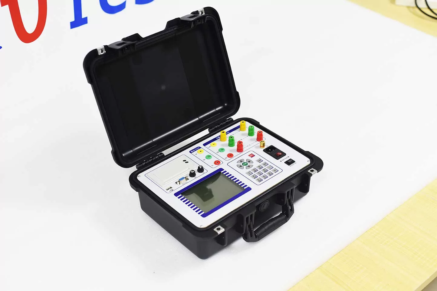
The no-load test of a transformer is primarily used to measure no-load current and no-load loss, which helps in analyzing the magnetic circuit of the iron core and the quality of construction. In practice, the high-voltage side of the transformer is left open-circuited, while the rated voltage at the rated frequency is applied to the low-voltage side. The choice to apply voltage to the low-voltage side is mainly based on considerations regarding test voltage, safety, and the configuration of test equipment.
1. The rated voltage for the low-voltage side is easier to obtain.
A no-load test requires the magnetic flux within the transformer core to approximate its state during normal operation; therefore, the rated voltage at the rated frequency must be applied to the energized winding.
If voltage were applied to the high-voltage side—for instance, in transformers with voltage ratings of 10 kV, 35 kV, or higher—it would necessitate high-voltage test power sources, voltage-regulating equipment, and measuring instruments of corresponding voltage classes, making the test system significantly more complex.
Conversely, applying voltage to the low-voltage side requires a much lower test voltage. For example, for a 10/0.4 kV distribution transformer, a no-load test only requires the application of a 400 V rated voltage, making it easier to secure a stable test power source.
2. It reduces insulation requirements for test equipment.
If a no-load test were performed from the high-voltage side, the voltage regulator, voltmeters, power-measuring instruments, and connecting leads would all need to withstand high voltages, necessitating higher insulation ratings for the test equipment. By applying voltage to the low-voltage side, the entire measurement system operates at a relatively lower voltage level, which lowers the insulation requirements for the test equipment and simplifies wiring and measurement procedures. This is a key reason why the low-voltage side is typically chosen for excitation during transformer no-load tests.
3. It enhances safety during on-site operations.
Although there is no load connected to the transformer’s output side during a no-load test, the transformer remains in an excited state, meaning a high voltage will be induced on the high-voltage side. By applying voltage to the low-voltage side, the components used for voltage regulation, measurement, and operation are kept on the lower-voltage side, thereby reducing the risk of personnel coming into direct contact with high-voltage test circuits. It is important to note that although the test power supply is connected to the low-voltage side, the high-voltage windings will still develop a high induced voltage. Therefore, a sufficient safety distance must be maintained on the high-voltage side, and appropriate isolation and protective measures must be implemented in accordance with high-voltage testing requirements.
4. Basic Principles of No-Load Loss Measurement
No-load loss in a transformer primarily stems from hysteresis and eddy current losses within the iron core. As long as the test frequency is correct and the corresponding rated voltage is applied to the energized winding, the magnetic flux in the iron core can be established to a state approximating that of normal operation. Consequently, from a fundamental theoretical perspective, a no-load test can be conducted by energizing either the high-voltage or the low-voltage side. In practice, the low-voltage side is chosen because it requires a lower voltage, makes the test power supply easier to configure, imposes less stringent insulation requirements on the measuring equipment, and is more convenient to operate.
5. Other Considerations for No-Load Testing
During a no-load test, ensure that the frequency of the test power supply meets the specified requirements. Gradually increase the voltage to the target value rather than applying the rated voltage abruptly. Additionally, measure and record the three-phase voltage, current, and power. If the three-phase no-load currents are significantly unbalanced, or if the no-load loss deviates substantially from the factory or design specifications, further investigation is required—checking factors such as the test power supply, voltage waveform, wiring, and the condition of the transformer core. For transformers with varying capacities, voltage ratings, and structural designs, the specific test wiring and energization methods should adhere to relevant testing standards, product technical documentation, and the established test protocol.
Summary
Transformer no-load tests are typically conducted by energizing the low-voltage side. This is primarily because the lower rated voltage on this side makes the test power supply easier to source, reduces insulation requirements for voltage-regulation and measuring equipment, and renders on-site operations both more convenient and safer. However, energizing the low-voltage side does not mean the high-voltage side remains voltage-free; high voltages will still be induced in the high-voltage windings. Therefore, all operations must strictly comply with safety requirements for high-voltage testing.
Related Products





Latest News
-
 2026-10-16How can measurement errors in no-load tests be minimized?
 -
 2026-10-16What are the consequences of non-compliant short-circuit impedance?
 -
 2026-10-15What are the differences between insulation resistance, absorption ratio, and polarization index?
 - 2026-10-15What is the purpose of a transformer load test?
-
 2026-10-15What causes unstable results in transformer DC resistance tests?
