
Home » News » Company News
Digital CT Tester Supplier for Substation Commissioning
Before a substation, solar plant, wind farm, or battery energy storage system is energized, its current transformers must deliver accurate current signals to protection relays, meters, and monitoring equipment. A digital CT tester gives commissioning teams a practical way to check whether each CT is correctly connected and suitable for its assigned duty before the project moves to system testing and grid connection.
For projects with multiple CT cores, feeder circuits, protection panels, and metering points, the testing process also needs clear parameter settings, reliable connections, and records that can be reviewed during handover. Kvtester provides CT/PT testing equipment for these field applications, including solutions for ratio, polarity, excitation, secondary resistance, burden, and error-related testing.
This guide explains how a digital CT tester can be used within a substation commissioning workflow. It covers test preparation, connection checks, parameter settings, ratio and polarity verification, excitation testing, burden measurement, result review, and the additional system tests required before energization.
Why CT Testing Is Required Before Energization
A current transformer reduces primary current to a secondary signal that can be measured safely by meters and used by protection relays. If the CT ratio, polarity, excitation performance, connected burden, or secondary wiring is incorrect, the protection or metering system may receive inaccurate information.
In a conventional or renewable energy substation, CT testing is commonly required for:
- Main transformer high-voltage and low-voltage side CTs
- Busbar and feeder protection CTs
- Collector feeder CTs in solar and wind power projects
- Grid interconnection point CTs
- BESS transformer and power conversion system feeder CTs
- Revenue metering and check metering CTs
- GIS, switchgear, bushing, and outdoor CT installations
A digital CT tester supports the verification of CT ratio, polarity, winding resistance, excitation characteristics, knee point voltage, burden, ratio error, and phase displacement. These results help commissioning teams confirm whether the CT is suitable for its intended metering or protection duty before the system is energized.
What a Digital CT Tester Can Verify
A digital CT tester assesses CT performance through controlled testing from the secondary side. It is useful during pre-commissioning, commissioning, maintenance, troubleshooting, and factory acceptance work.
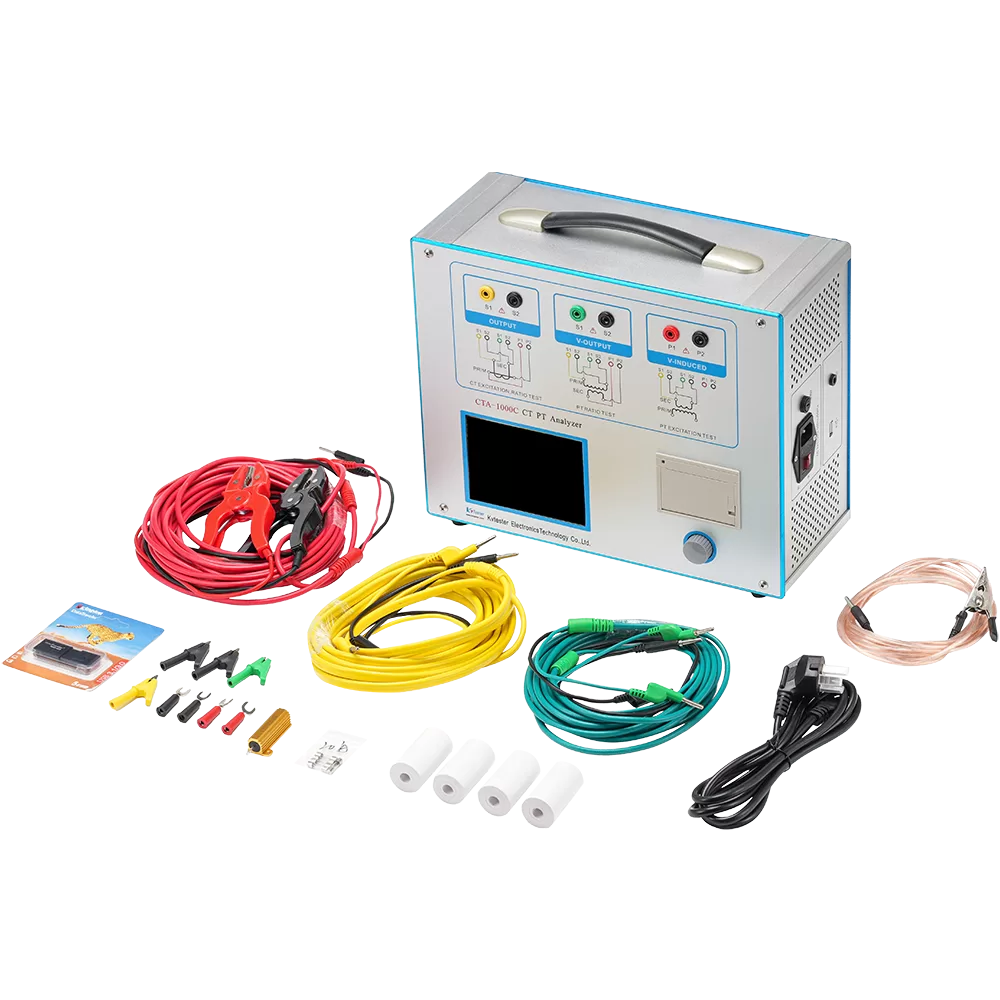
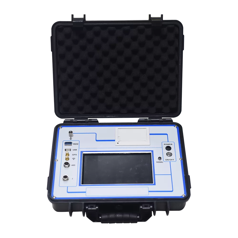
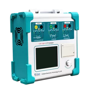
The CTA-1000C CT/PT Analyzer is designed for CT and PT testing in power system applications. It supports ratio and phase-angle testing, excitation and saturation characteristics, burden impedance, winding resistance, CT polarity, saturated and unsaturated inductance, residual magnetism, ALF, and FS evaluation. This makes it suitable for field testing of metering and protection CTs as well as transformer and switchgear manufacturing checks.
For CT testing, the CTA-1000C supports:
- CT ratio testing from 1 to 40000
- CT ratio accuracy of ±0.05%
- Secondary winding resistance testing from 0 to 300 Ω
- AC burden testing from 0 to 1000 VA
- Excitation characteristic and knee point testing
- Polarity, ratio error, and phase displacement testing
- CT types including metering, P, PR, PX, TPY, TPS, TPX, and TPZ classes
- Analysis of 10% error curves, accuracy limit factor, instrument security factor, secondary time constant, and remanence coefficient where applicable
A CT tester does not replace all commissioning equipment. It verifies important CT characteristics, but a complete substation commissioning program may also require insulation testing, primary injection, secondary injection, relay protection testing, functional logic checks, trip circuit verification, SCADA checks, and meter validation.
Prepare Safely Before CT Testing
CT testing must be completed by qualified electrical testing personnel under the approved project safety plan. The team should review the single-line diagram, protection drawings, CT secondary schematics, terminal diagrams, test procedures, and CT nameplate data before connecting the tester.
Before starting, confirm the following:
- The relevant equipment is isolated according to the project’s lockout/tagout procedure
- The work permit and switching procedure allow CT testing
- The CT primary circuit and connected equipment are in the required safe condition
- The tester and CT are reliably grounded
- The selected CT core matches the intended protection or metering circuit
- The CT ratio, secondary current, class, burden, and power factor are taken from the nameplate and engineering documents
- Secondary terminals, shorting links, grounding points, and test blocks have been checked against the drawings
- Test leads are connected before testing begins and are not connected or disconnected while the test is running
Keep the tester reliably grounded throughout the work. Do not use the equipment in wet or explosive environments, do not touch exposed energized parts, and do not connect or disconnect test leads while a test is running.
CT secondary circuits also require special attention. An energized CT secondary circuit must not be left open because hazardous voltage can develop. Commissioning personnel should follow the approved secondary-circuit isolation, shorting, grounding, and reconnection procedure for the specific installation.
Step 1: Identify the CT Core and Test Scope
Many substation CTs contain multiple secondary cores. Each core may serve a different purpose, such as revenue metering, protection, bus differential protection, transformer differential protection, overcurrent protection, or backup protection.
Start by identifying:
- CT location and equipment reference number
- CT manufacturer, model, serial number, and nameplate data
- Primary and secondary rated current
- CT ratio and available taps
- Accuracy class and core designation
- Rated burden and power factor
- Application of each secondary core
- P1/P2 and S1/S2 terminal markings
- Required test items under the project specification
Protection and metering cores should be tested and documented separately. A protection CT may require excitation curve, knee point, saturation, and transient performance testing, while a metering CT may place greater emphasis on ratio error, phase displacement, burden, and accuracy performance.
For multi-ratio CTs, identify each required tap before testing. Use the term multi-tap detection when describing this process, rather than implying that all taps can be tested through a single automatic action.
Step 2: Connect the Digital CT Tester
Correct wiring is essential for valid results. Connect the tester according to the selected test function and the CT structure.
For standard CT testing, connect the instrument output and measurement leads to the selected CT secondary terminals. When ratio, excitation, or resistance measurement requires higher accuracy, use the four-terminal connection method to reduce the influence of lead resistance.
The four-terminal method separates the current path from the voltage measurement path. This helps measure the actual voltage across the winding rather than the voltage drop across the test leads. Use this connection method for resistance, ratio, and excitation testing when the selected instrument wiring diagram requires it.
For special installations, follow the correct procedure for the CT type:
- Bushing CTs: Confirm the required primary-side disconnection condition before testing. For the applicable bushing CT arrangement, disconnect the H1 terminal first so that the test circuit can obtain valid results.
- GIS CTs: Confirm that relevant connections are isolated and that grounding switches are in the required position according to the approved project procedure before testing.
- Switchgear CTs: Verify the test block, shorting arrangement, relay panel terminals, and core selection before connecting the tester.
- Outdoor CTs: Protect the tester from rain, excessive heat, and blocked ventilation during outdoor commissioning.
Step 3: Enter CT Nameplate Parameters
After the test connections are verified, enter the correct CT parameters into the digital CT tester. Accurate settings are important because the tester uses the entered information to calculate and evaluate applicable CT results.
Typical parameters include:
- CT type and class
- Rated primary current
- Rated secondary current, usually 1 A or 5 A
- Rated burden
- Burden power factor
- Rated frequency, 50 Hz or 60 Hz
- Ambient temperature
- Rated accuracy limit factor for applicable protection CTs
- Instrument security factor for metering CTs
- Short-circuit current factor and time constants for applicable transient CT classes
The CTA-1000C supports parameter settings for P, TPY, metering, PR, PX, TPS, TPX, and TPZ CTs. Different CT classes require different nameplate and application parameters for the calculation of ratio error, phase error, limiting electromotive force, ALF, FS, transient dimensioning factors, and related values.
Step 4: Test Secondary Winding Resistance
Secondary winding resistance testing checks the continuity and condition of the CT secondary winding. It can help identify loose terminal connections, poor joints, unexpected wiring resistance, or potential winding issues.
During commissioning, record:
- Measured resistance at the current ambient temperature
- Resistance converted to the applicable reference temperature when required
- CT core and tap identification
- Test lead configuration
- Comparison against factory data, project limits, or comparable cores
The CTA-1000C measures secondary resistance from 0 to 300 Ω with an accuracy of 0.2% ±2 mΩ.
If a result is abnormal, do not proceed directly to other tests. First inspect the selected terminals, shorting links, test-lead contacts, and connection points. For new renewable energy projects, this check is especially useful where long secondary cables, multiple panels, or late-stage wiring changes may affect the installed circuit.
Step 5: Test Excitation Characteristics and Knee Point Voltage
Excitation testing is important for protection CTs because it indicates how the CT core responds as it approaches saturation. Protection systems require reliable current reproduction during fault conditions, and CT saturation can affect relay performance.
A digital CT tester can measure the excitation characteristic and determine the knee point voltage and current. For applicable CT classes, it can also provide data related to saturation, ALF, remanence, and transient performance.
The CTA-1000C uses a low-frequency test method. By reducing the test frequency while maintaining the required magnetic flux condition, the method can reduce the required test voltage on the CT secondary winding. The instrument can evaluate CTs with knee point voltages up to 60 kV.
When reviewing excitation results, compare them with:
- CT nameplate values
- Protection design requirements
- Manufacturer test data
- Engineering calculations for connected burden and fault duty
- Project requirements for PX, PR, TPY, TPS, TPX, or TPZ CT applications
Use transient performance testing for the appropriate CT classes and protection duties. This terminology is more accurate than “dynamic performance testing” for CT-related technical content.
Step 6: Verify CT Ratio and Polarity
CT ratio and polarity tests are fundamental commissioning checks. They confirm that the CT is connected with the intended transformation ratio and current direction.
A ratio test verifies that the measured ratio matches the CT nameplate and the value used in relay settings, metering configuration, and SCADA calculations. A polarity test verifies the relationship between the primary and secondary terminals.
Incorrect polarity may affect:
- Transformer differential protection
- Bus differential protection
- Directional overcurrent protection
- Feeder protection
- Power and energy metering
- Synchronizing and monitoring calculations
The CTA-1000C supports CT ratio testing from 1 to 40000, with ±0.05% accuracy. It can also display polarity, ratio difference, and phase difference results for applicable CT tests.
If a polarity result is incorrect, verify the CT terminal markings, protection schematic, terminal block wiring, cable core identification, and relay input configuration. Do not resolve a polarity problem by changing conductors without confirming the complete protection and metering circuit design.
Step 7: Measure the Actual Secondary Burden
The burden connected to a CT includes the resistance and impedance of secondary cables, relays, meters, test switches, transducers, and other connected devices. The actual burden should be evaluated against the CT’s rated burden and the assumptions used in protection or metering design.
A burden test helps answer practical commissioning questions:
- Does the installed secondary circuit exceed the CT rated burden?
- Has a long cable route increased the circuit burden?
- Does the measured burden match the engineering design?
- Could connected equipment affect CT accuracy or protection performance?
- Are additional relays, meters, or monitoring devices increasing the load?
The CTA-1000C measures AC burden from 0 to 1000 VA and can provide burden, power factor, and impedance-related results.
This is particularly relevant in solar, wind, and BESS projects, where CT secondary circuits may run between outdoor switchgear, collector feeders, control buildings, protection panels, metering cubicles, and grid interconnection equipment.
Step 8: Review Results Before Moving to System Tests
A commissioning report should not simply state “pass” or “fail.” It should record the measured data, the acceptance reference, the tested CT core, the test configuration, and the action required for abnormal results.
Common findings and next actions include:
- Ratio does not match design: Verify CT tap selection, nameplate data, wiring, relay settings, and meter configuration
- Polarity result is incorrect: Review P1/P2 and S1/S2 connections, wiring diagrams, terminal schedules, and relay input direction
- Winding resistance is abnormal: Check terminal tightness, wiring continuity, connectors, and CT winding condition
- Measured burden is too high: Review cable length, relay inputs, connected equipment, and the selected CT burden rating
- Knee point voltage is below the required value: Escalate for engineering review of CT suitability, burden, fault duty, and protection application
- Excitation curve is inconsistent: Confirm the CT core, test connection, remanence condition, and manufacturer reference data
- Phase or ratio error is outside the expected range: Review the CT accuracy class, burden, temperature, and use of the CT for metering or protection
The CTA-1000C can display CT results including resistance, load, power factor, impedance, knee voltage/current, inductance, remanence coefficient, second time constant, ALF, FS, ratio, ratio difference, phase difference, and polarity, depending on the selected CT class and test configuration.
Digital CT Tester and Primary Injection Testing
A digital CT tester and a primary injection test set serve different purposes in commissioning.
A CT tester evaluates the CT itself and its secondary-side characteristics. It is used for ratio, polarity, winding resistance, excitation, burden, saturation-related values, and error analysis.
Primary injection testing is used to verify the complete current path from the primary conductor through the CT, secondary wiring, protection relay input, logic scheme, and, in some cases, the final trip circuit. It is normally performed after the relevant secondary circuits and relay settings are ready for end-to-end verification.
For a complete substation or renewable energy commissioning plan:
- Use the CT tester to verify CT characteristics and selected secondary-side parameters
- Confirm secondary wiring, grounding, terminal identification, and core assignment
- Perform relay protection and control checks
- Use primary injection where required to validate the complete protection path
- Finalize test records before energization and grid connection
This sequence helps distinguish a CT performance issue from a wiring, settings, relay, logic, or trip-circuit issue.
Renewable Energy Project Considerations
Renewable energy projects often involve tight energization schedules, multiple contractors, repeated equipment configurations, and detailed utility acceptance requirements. CT testing records should therefore be consistent, traceable, and linked to the final protection and metering documentation.
Solar PV Substations
For solar projects, confirm CT configuration at inverter transformer feeders, collector circuits, main transformers, station service transformers, and the grid connection point. Test records should clearly distinguish CTs used for feeder protection, transformer protection, export metering, and check metering.
Wind Farm Collector Systems
Wind projects may include multiple turbine feeders, collector circuits, ring connections, and a central substation. Consistent CT naming, phase identification, polarity verification, and burden documentation help reduce commissioning delays across similar feeder bays.
Battery Energy Storage Systems
BESS projects require clear CT allocation for PCS feeders, battery transformers, station transformers, auxiliary systems, and the point of common coupling. The CT test report should identify the function of each core and confirm the associated protection or metering circuit.
GIS and Bushing CT Applications
GIS and bushing CTs require extra attention because access and isolation conditions differ from conventional outdoor CTs. Follow the approved switching procedure and the relevant CT test connection instructions. Use the appropriate connection method for bushing and GIS CT testing.
Document Every CT Test
Commissioning documentation should support project handover, utility acceptance, future troubleshooting, and periodic maintenance. Keep a record of:
- Project and substation name
- Bay, feeder, transformer, or grid connection location
- CT manufacturer, model, serial number, and nameplate data
- CT core designation and intended application
- Tester model and calibration status
- Test date, operator, ambient temperature, and test configuration
- Resistance, excitation, knee point, ratio, polarity, burden, and error results
- Abnormal findings, corrective actions, and retest results
- Related primary injection and relay protection test references
The CTA-1000C can store test data and copy it to a PC through a USB disk for analysis and Word report preparation. Use the stored data and exported files to organize test records and support the final commissioning report.
Select the Right CT Testing Solution
The correct CT testing approach depends on the CT type, protection application, metering class, test standard, site environment, and commissioning scope. For individual CT and PT field testing, a portable analyzer can support ratio, polarity, excitation, burden, resistance, and error evaluation. For batch verification of current transformers in manufacturing or laboratory environments, a complete automated system may be more suitable.
The ZCHG-12 CT/PT Test System supports automated current transformer verification requirements. It can be configured with an intelligent transformer calibrator, burden boxes, a variable-frequency power supply, a CT test bench, and management software. With computer-based parameter settings and RS485 control, one primary-current operation can measure up to 12 current transformers with the same ratio, helping improve batch testing efficiency for CT manufacturers and testing laboratories.
Before selecting equipment, provide the supplier with the CT nameplate data, intended protection or metering application, required standards, testing location, secondary current rating, required ratio range, and commissioning procedure. This enables the test configuration to match the actual requirements of the substation, solar plant, wind farm, or BESS project.
Related Products





Latest News
-
 2026-09-22Smart ANSI Standard PT Tester For Grid Applications
 -
 2026-09-21Smart Transformer Testing Equipment: Features for Efficient Testing
 -
 2026-09-21Transformer Testing Equipment for Grid Maintenance Guide
 -
 2026-09-20CT PT Analyzer for Commissioning: Substation Testing Guide
 -
 2026-09-20ANSI Standard CT Tester: Specs, Tests & Buying Guide
