
Home » News » Company News
Smart ANSI Standard PT Tester For Grid Applications
How can you test a potential transformer accurately in a power grid environment? Which PT tests should be completed before a transformer is put into service? How can excitation, saturation, polarity, burden, and winding resistance be checked efficiently without making field testing unnecessarily complicated?
For engineers working with substations and grid equipment, the challenge is not simply completing individual measurements. The testing process also needs to be repeatable, efficient, and suitable for actual power system maintenance and commissioning conditions.
This is where a Smart ANSI Standard PT Tester For Grid can become useful. The key is understanding how the tester should be connected, which tests should be performed, and how the results should be interpreted during practical PT testing.
Why a Smart PT Tester Matters for Grid PT Testing
Grid PT testing often involves several related measurements rather than a single test. A suitable testing system should allow engineers to move between different test functions without rebuilding the entire setup each time.
For teams working with CT/PT test equipment, the testing workflow can be organized around the actual characteristics that need to be verified. This makes it easier to maintain consistency between commissioning work, routine maintenance, and troubleshooting.
The main testing areas normally include excitation characteristics, saturation behavior, polarity, burden, and winding resistance. Each test provides different information, so the sequence and connection method matter.
PT Testing Before Using a Smart ANSI Standard PT Tester For Grid
Before connecting the instrument, we recommend confirming the transformer nameplate data, winding configuration, rated values, and test requirements for the project.
The test area should also be isolated according to applicable safety procedures. Unnecessary connections should be removed, and transformer terminals should be identified before test leads are connected.
For grid maintenance teams, the working environment can vary considerably between a laboratory, substation, and field maintenance location. Equipment used for power construction and maintenance enterprises therefore needs to support a practical workflow rather than only laboratory-style testing.
Once the transformer information and test conditions have been confirmed, the next step is establishing the correct electrical connection.
Connecting the PT Tester for Grid Applications
The connection method depends on the specific PT winding and the test being performed. Before starting a measurement, we recommend checking that the selected terminals correspond to the intended winding and that all unused connections are safely isolated.
A clear connection procedure helps reduce incorrect readings caused by loose leads, wrong terminal selection, or an unsuitable test configuration.
For a Smart ANSI Standard PT Tester For Grid application, the connection stage should also consider field conditions. Limited working space, long test leads, and repeated testing can all affect how efficiently the testing process is carried out.
After the connection is confirmed, excitation and saturation testing can provide important information about the magnetic characteristics of the PT.
PT Excitation and Saturation Testing
Excitation testing helps engineers evaluate how the transformer behaves as the applied voltage increases. The resulting curve can provide useful information about the magnetic characteristics of the core.
PT Excitation Testing
During excitation testing, the test voltage is gradually increased while the corresponding current is measured. The resulting relationship helps identify changes in the transformer’s magnetic behavior.
When comparing results, it is important to use consistent test conditions and consider the transformer’s rated parameters. A stable and repeatable measurement process makes the results easier to review and compare.
PT Saturation Testing
Saturation testing focuses on the point at which the core begins to enter a significantly nonlinear operating region.
A Smart PT Tester can simplify this process by controlling the test output and recording measured values during the test. This reduces the need for manual adjustment and makes the test sequence easier to repeat.
Once the excitation characteristics have been checked, other electrical characteristics should be considered.
PT Polarity, Burden, and Winding Resistance
Excitation and saturation characteristics are only part of a complete PT testing workflow. Polarity, burden, and winding resistance provide additional information about the condition and connection of the transformer.
PT Polarity Testing
Polarity testing confirms the relationship between the primary and secondary winding terminals. Correct polarity is important when the PT is connected to protection, measurement, or control circuits.
During testing, the terminal configuration should be checked carefully against the transformer documentation.
PT Burden Testing
Burden testing evaluates the load connected to the secondary circuit. Excessive or unsuitable burden can affect the performance of the measurement circuit.
For grid applications, checking burden can be particularly useful when the PT is integrated with meters, protection devices, or other secondary equipment.
PT Winding Resistance
Winding resistance testing provides another way to identify abnormal conditions in the winding and connection path.
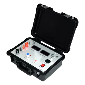
For example, our CTA-1000D CT/PT analyzer provides 1 mΩ winding resistance resolution, with typical accuracy of 0.05%. Its compact 9 kg instrument body also supports practical field use when multiple measurements are required.
These specifications are useful when selecting equipment for applications where resistance measurements need to be performed alongside other PT tests.
What to Look for in Smart ANSI Standard PT Tester For Grid Equipment
When selecting testing equipment, we recommend looking beyond a single specification. The more important question is whether the equipment can support the complete testing workflow required by your project.
Several factors deserve attention:
- Test functions: Check whether the equipment supports the PT measurements required for your application.
- Measurement resolution: Higher resolution can be important when small changes need to be identified.
- Test automation: Automated sequences can reduce repetitive manual operations.
- Field portability: Weight and physical dimensions matter when equipment is moved between substations.
- Test consistency: Repeatable test procedures make results easier to compare.
- Operating conditions: Check whether the instrument is suitable for the expected temperature and power supply environment.
For example, the CTA-1000D has a stated operating temperature range of -10°C to +50°C, dimensions of 370 × 320 × 170 mm, and a weight of 9 kg without accessories. These specifications can be considered when planning field testing work.
Smart PT Testing in Power Grid Field Applications
Field testing places different demands on equipment than controlled laboratory testing. Engineers may need to transport the tester between substations, complete several measurements in sequence, and work within limited space.
A practical Smart PT Tester should therefore fit naturally into the existing workflow.
In power grid applications, testing may take place during commissioning, scheduled maintenance, troubleshooting, or equipment replacement. The required test sequence can vary, but the goal remains the same: obtain reliable measurements while keeping the testing process controlled and efficient.
How a Smart ANSI Standard PT Tester For Grid Streamlines Field Work
Automation becomes especially useful when several related measurements must be completed on the same transformer.
Instead of manually adjusting test parameters and recording every measurement separately, an integrated PT testing system can combine measurement, control, and result processing in a more consistent workflow.
Our CTA-1000D, for example, provides automated testing functions and a stated automatic test duration of less than 2 minutes for applicable test operations. Its output specifications include 0–120 V test voltage, 0–5 A RMS / 15 A peak output current, and up to 400 VA RMS / 1500 VA peak output power.
The value of these specifications depends on the actual PT and test requirements. Equipment selection should always be based on the required test range rather than on output capability alone.
Choosing a Smart ANSI Standard PT Tester For Grid Applications
The right tester should match the transformer type, required measurements, working environment, and expected testing frequency.
If the application requires multiple PT measurements in the field, an integrated instrument can reduce the number of separate test setups. If portability is important, physical size and weight should be considered together with the required functions.
For projects where a more detailed evaluation of CT/PT testing capabilities is needed, the CTA-1000D CT/PT analyzer provides a practical reference for evaluating functions such as excitation and saturation testing, polarity, burden impedance, and winding resistance.
The final selection should come from the actual testing requirements rather than from one specification alone. A well-matched Smart ANSI Standard PT Tester For Grid can make field PT testing more structured, repeatable, and efficient.
When your project involves specific transformer types, test requirements, or field conditions, contact our technical team to discuss the appropriate testing configuration.
Related Products





Latest News
-
 2026-09-22Digital CT Tester Supplier for Substation Commissioning
 -
 2026-09-21Smart Transformer Testing Equipment: Features for Efficient Testing
 -
 2026-09-21Transformer Testing Equipment for Grid Maintenance Guide
 -
 2026-09-20CT PT Analyzer for Commissioning: Substation Testing Guide
 -
 2026-09-20ANSI Standard CT Tester: Specs, Tests & Buying Guide
