
Home » News » Company News
ANSI Standard CT Tester: Specs, Tests & Buying Guide
ANSI/IEEE current transformer projects are defined by the duty assigned to the CT. Protection schemes, metering circuits, connected burden, fault-current conditions, and the required evaluation method all influence the test data that engineers need to review.
An ANSI standard CT tester should support the applicable test process for the CT under evaluation. That includes appropriate parameter entry, measurement capability, calculation functions, and test records for the selected ANSI/IEEE or IEC workflow.
Separate Protection and Metering Duties
Protection CTs and metering CTs serve different functions in the power system. Their evaluation should therefore focus on different results.
For protection CT applications, engineers may need excitation characteristics, knee-point voltage and current, secondary winding resistance, burden, saturation-related information, 5% or 10% error curves, accuracy limit factor, transient parameters, and remanence-related results. The exact requirement depends on the CT class, protection scheme, project specification, and selected evaluation method.
For metering CT applications, the key concerns often include ratio, ratio error, phase displacement, polarity, burden, power factor, and the accuracy behavior required by the metering arrangement.
An instrument that performs a basic ratio test may be useful for limited checks, but it does not necessarily provide the data needed for a protection CT evaluation or a metering accuracy review.
Define the Required Standard Setting
A standards label should be supported by a clear explanation of how the tester applies the selected method. Ask whether the equipment can accept the relevant CT nameplate data, calculate the intended values, and produce results that can be reviewed against project criteria.
For CT projects, IEC 61869-1 and IEC 61869-2 are key references for instrument-transformer requirements. ANSI/IEEE projects may require an evaluation process that uses the applicable IEEE setting and the nameplate parameters relevant to the selected CT duty.
The CTA-1000C parameter interface includes CT categories for R-IEC, R-ANSI, M-IEC, M-ANSI, P, TPY, PR, PX, TPS, TPX, and TPZ-related settings. The applicable parameter fields vary by CT type and may include rated primary current, rated burden, power factor, accuracy-limit-related values, instrument security factor, short-circuit-current coefficient, primary time constant, secondary time constant, and duty cycle information.
Focus on the Required Results
The measurement list should be built around the engineering decision that the test must support.
For a protection CT, the required data may include:
- Excitation curve
- Knee-point voltage and current
- Secondary winding resistance
- Actual secondary burden
- Burden power factor and impedance
- Ratio and polarity
- Actual ALF where applicable
- 5% or 10% error curve
- Remanence coefficient
- Secondary time constant
- Transient performance testing results for applicable CT classes
For a metering CT, the focus may include:
- Actual ratio and turns ratio
- Ratio difference
- Phase difference
- Polarity
- Secondary burden
- Burden power factor
- Secondary winding resistance
- Applicable error results under the selected test conditions
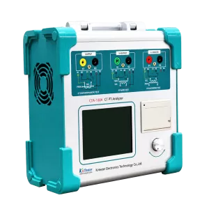
The CTA-1000C CT/PT Analyzer supports CT excitation characteristics, ratio, polarity, secondary winding resistance, secondary burden, ratio error, and phase displacement. Depending on CT class and selected parameters, it can also provide results including knee-point voltage/current, 10% error curves, ALF, FS, secondary time constant, remanence coefficient, and saturated or unsaturated inductance.
Review Output and Measurement Ranges
A tester should have sufficient capability for the CTs being evaluated. The decision should be based on the actual CT ratio, excitation characteristics, winding resistance, rated burden, installed secondary circuit, and project test procedure.
CTA-1000C provides 0–180 Vrms output, 12 Arms output current, and 36 A peak current. Its CT ratio test range is 1–40,000 with stated accuracy of ±0.05%. Secondary resistance measurement covers 0–300 Ω with stated accuracy of 0.2% ± 2 mΩ. AC burden measurement covers 0–1000 VA with stated accuracy of 0.2% ± 0.02 VA.
The analyzer uses a low-frequency test method for CT testing. Under the relevant magnetic-flux condition, reducing the frequency can reduce the required test voltage on the CT secondary winding. The published capability covers CT knee-point voltage testing up to 60 kV.
Verify the Parameter Workflow
The test result depends on correct parameter entry. An ANSI/IEEE CT tester should allow the operator to enter the information needed for the intended CT evaluation.
- CT class and application
- Rated primary and secondary current
- Rated burden and power factor
- CT ratio and tap
- Rated frequency
- Test temperature where resistance conversion is required
- Maximum measuring current
- ALF or FS values when applicable
- Short-circuit and time-constant values for applicable transient CT work
- The selected standard setting
- Required acceptance criteria
Different CT classes use different calculations. For this reason, a valid evaluation process should not apply one universal parameter set to every CT.
Consider Reporting and Field Use
For on-site projects, engineers need a tester that supports orderly data collection as well as required measurements. CTA-1000C weighs less than 10 kg and operates from AC 220 V ±10%, 50/60 Hz. It can store up to 1,000 groups of test data, which can be copied to a PC through a USB disk for analysis and Word report preparation.
The test records should identify the CT, selected winding or tap, nameplate data, standard setting, test conditions, measured results, and reviewer decision. Equipment records should support the project’s internal reporting process; no direct PDF export capability should be assumed unless separately confirmed.
Kvtester provides CT/PT analyzers for protection, metering, commissioning, manufacturing, and laboratory applications. A suitable configuration begins with the CT class, selected standard method, required outputs, and the results needed for project acceptance.
Select Around the Evaluation Task
An ANSI standard CT tester should be chosen for the engineering evaluation it supports. A protection CT project may require excitation and error-curve analysis, while a metering CT project may need accurate ratio, phase, burden, and error data. The instrument, entered parameters, test procedure, and report format should all align with that task.
Provide the CT nameplate, intended duty, applicable standard setting, required test results, secondary current rating, expected burden, and field or laboratory conditions when requesting a configuration. That information helps define whether a portable analyzer, a higher-accuracy option, or a batch verification system is appropriate.
Related Products





Latest News
-
 2026-09-20CT PT Analyzer for Commissioning: Substation Testing Guide
 -
 2026-09-18Why does the required capacity of series resonant test equipment usually increase with cable length?
 -
 2026-09-18How should 35kV cable series resonant withstand voltage test equipment be configured?
 -
 2026-09-18How to Select AC Withstand Voltage Test Equipment for 10kV Cables?
 -
 2026-09-18What parameters must be provided to the manufacturer when purchasing series resonant withstand voltage test equipment?
