What Are the Test Parameters for a Comprehensive Instrument Transformer Test Bench?
The test parameters for a comprehensive instrument transformer test bench are the core metrics used to evaluate the performance of Current Transformers (CTs) and Voltage Transformers (PTs), encompassing various dimensions such as electrical characteristics, measurement accuracy, and safety performance. The following is a detailed classification and explanation of these test parameters:
1. Current Transformer (CT) Test Parameters
① Transformation Ratio Test
a. Definition: The ratio of the primary-side current to the secondary-side current (e.g., 1000A/5A).
b. Test Method: By applying a current to the primary side and measuring the resulting output current on the secondary side, the actual transformation ratio is calculated.
c. Parameter Requirements:
Ratio Error: ≤ ±0.2% (may reach ±0.05% for high-precision applications).
Polarity: Identifies the phase relationship between the primary and secondary sides (either same-polarity or reverse-polarity).
② Volt-Ampere Characteristic Test
a. Definition: The characteristic curve illustrating the relationship between the secondary-side excitation current and excitation voltage; this reflects the saturation characteristics of the iron core.
b. Test Method: The secondary-side voltage is gradually increased while recording the corresponding excitation current to plot the Volt-Ampere characteristic curve.
c. Parameter Requirements:
Knee-point Voltage: The voltage value at which the iron core begins to saturate (typically 1.5 to 2 times the rated secondary voltage).
Saturation Multiple: The multiple of the rated secondary voltage reached at the knee-point, relative to the voltage produced by the rated primary current (e.g., 10 times).
③ Error Test
a. Definition: Includes both ratio error and phase error, reflecting the deviation between the actual output of the instrument transformer and its theoretical value.
b. Test Method: Under rated load conditions and at various power factors, a primary-side current is applied, and the magnitude and phase difference of the secondary-side voltage/current are measured.
c. Parameter Requirements:
Ratio Error: ≤ ±0.1% (for Class 0.2 CTs) or ≤ ±0.2% (for Class 0.5 CTs).
Phase Error: ≤ ±2 minutes (for Class 0.2 CTs) or ≤ ±10 minutes (for Class 0.5 CTs).
Load Range: Errors are typically tested at 25%, 50%, 75%, 100%, and 120% of the rated load. ④ Secondary Circuit Impedance Test
a. Definition: The DC resistance of the secondary winding, which affects the instrument transformer’s load capability and error characteristics.
b. Test Method: The four-terminal method is used to measure the secondary-side DC resistance.
c. Specification Requirements:
Impedance Value: Typically ≤ 0.1 Ω (the specific value depends on the model).
Temperature Coefficient: The stability of the impedance as it varies with temperature (e.g., ≤ 0.01 Ω/°C).
⑤ Demagnetization Test
a. Definition: The elimination of residual magnetic flux in the instrument transformer’s iron core to prevent measurement errors.
b. Test Method: Demagnetization is performed by applying a reverse DC or AC magnetic field.
c. Specification Requirements:
Post-Demagnetization Error: The error after demagnetization should recover to within ±50% of the initial value.
2. Voltage Transformer (PT) Test Specifications
① Transformation Ratio Test
a. Definition: The ratio of the primary-side voltage to the secondary-side voltage (e.g., 10 kV / 100 V).
b. Test Method: Apply voltage to the primary side, measure the output voltage on the secondary side, and calculate the actual transformation ratio.
c. Specification Requirements:
Transformation Ratio Error: ≤ ±0.2% (for Class 0.2 PTs) or ≤ ±0.5% (for Class 0.5 PTs).
Polarity: Identifies the phase relationship between the primary and secondary sides (same polarity or reverse polarity).
② No-Load Error Test
a. Definition: The error in the secondary-side voltage measurement when the primary side is energized at its rated voltage while the secondary side is open-circuited.
b. Test Method: At the rated frequency, apply voltage to the primary side up to its rated value, and record the secondary-side voltage.
c. Specification Requirements:
No-Load Error: ≤ ±0.2% (for Class 0.2 PTs) or ≤ ±0.5% (for Class 0.5 PTs).
③ Load Error Test
a. Definition: The error in the secondary-side voltage measurement when the rated load is connected to the secondary side.
b. Test Method: At the rated frequency and rated voltage, connect various loads (e.g., 25%, 50%, and 100% of the rated load) and measure the secondary-side voltage. c. Performance Specifications:
Load Error: ≤ ±0.2% (for Class 0.2 PTs) or ≤ ±0.5% (for Class 0.5 PTs).
Load Range: Typically, errors are tested at 0%, 25%, 50%, 75%, 100%, and 120% of the rated load.
④ Insulation Performance Testing
a. Definition: To evaluate the dielectric strength of the insulation between the primary and secondary sides of the instrument transformer.
b. Test Methods:
Power-Frequency Withstand Voltage: Apply a 50 Hz AC voltage (e.g., applying 28 kV for 1 minute between the primary side and the secondary side/ground).
Partial Discharge Test: Detect the partial discharge magnitude at 1.2 times the rated voltage (e.g., ≤ 5 pC).
c. Performance Specifications:
Insulation Resistance: ≥ 1000 MΩ (measured using a 500 V megohmmeter).
Withstand Voltage Value: Must comply with the requirements of the GB/T 20840.3 standard.
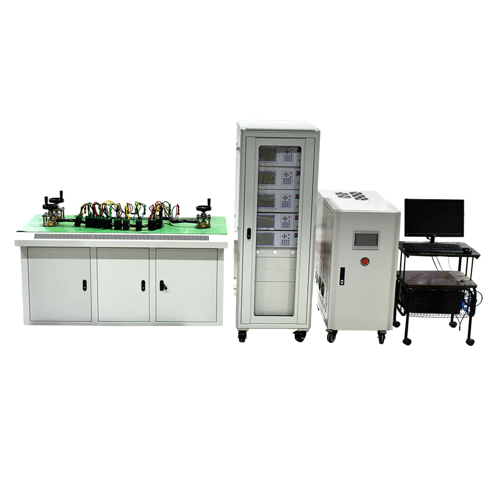
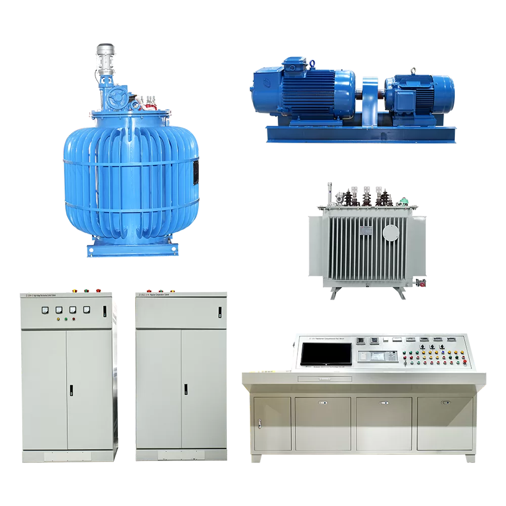
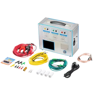
The ZCHG-12 CT PT Test System is a new generation of transformer fully automatic accuracy testing system developed by our company to adapt to the fast and accurate characteristics of modern current transformer calibration. The device consists of a transformer calibrator, a programmable current transformer load box, a variable frequency power supply, and a high-speed transformer test bench. The operator can set the main parameters of the tested transformer, such as type, range, accuracy level, secondary load, power factor, and transformer station position, through the computer error verification management software. By transmitting and controlling through RS485, the measurement work of 12 current transformers with the same ratio can be completed at once, greatly improving work efficiency.
Kvtester Electronics Technology Co.,Ltd. is a high-tech enterprise specializing in power testing, testing, research and development, production, and sales of testing equipment. It has been engaged in the electrical testing industry for many years, and its products are of high quality. We welcome customers to come and purchase. Service hotline: 0086-27-81778799, to learn more, visit the official website: www.kvtester.com
Related Products
Lasted News
-
 2026-07-24How to Select a Transformer Comprehensive Test Bench?
 -
 2026-07-24Comprehensive Overview of Transformer Factory Acceptance Tests
 -
 2026-07-24How to Choose Multi-function CT Tester | CTA-1000D vs OMICRON
 -
 2026-07-24What Are CT Testers & Working Principle in Transformer Factory
 -
 2026-07-24How to Test Current Transformers with a CT Analyzer