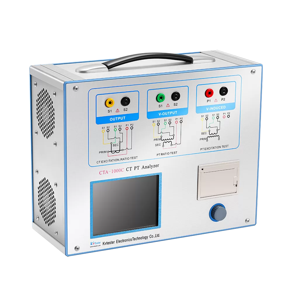
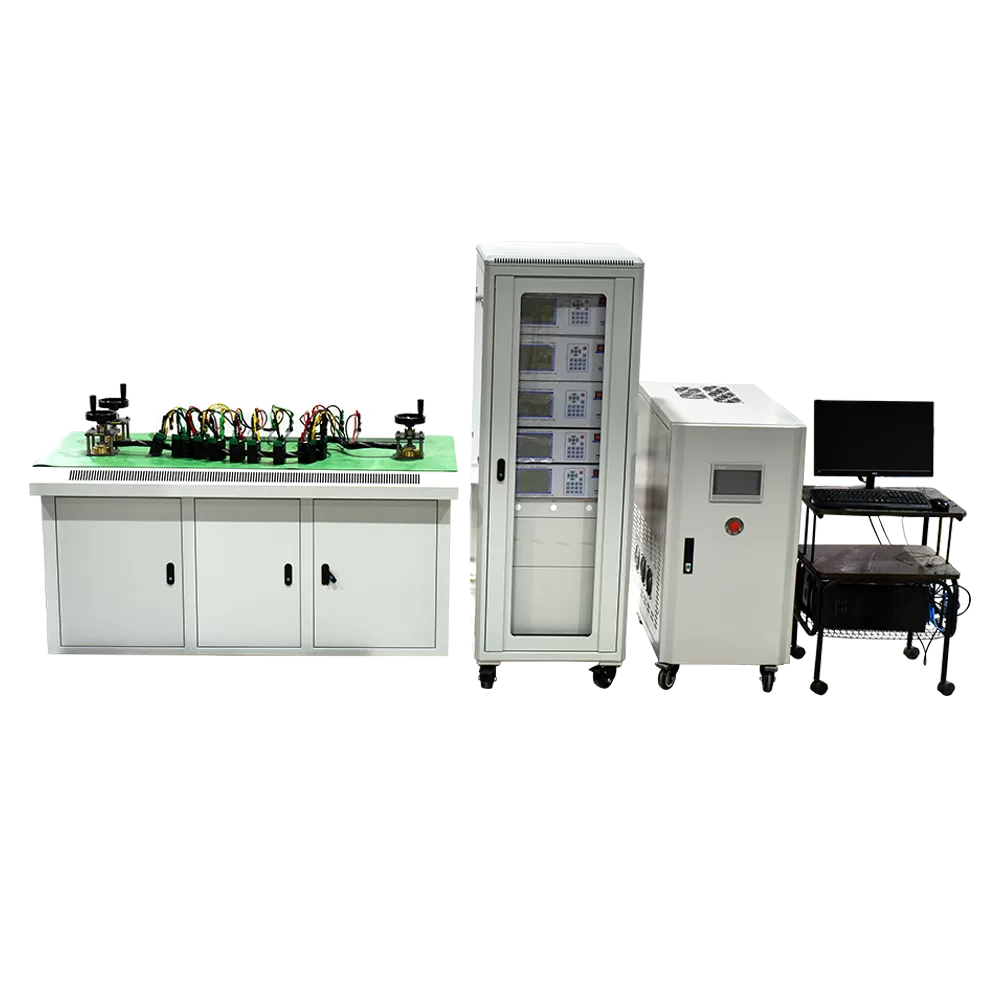
CTA-1000C CT PT Analyzer Actual Connection Method
CTA-1000C CT PT Analyzer is new product created after widely adopt customers’ advises and deep theoretical study. It is based on the automatic FA Series Transformer Tester General which is produced by our company that is widely acclaimed and applied. The adoption of high-performance DSP and ARM, advanced manufacturing technology ensure a stable and reliable product performance, full-featured, high degree of automation, high efficiency, in the domestic leading level, they are the professional testing equipment for transformer check in power industry.
CTA-1000C CT PT Analyzer for the CT test the basic connection steps (see Figure D.1) as follows:
① 4mm2 line the left side of CTA-1000C is connected to the grounding terminal protected.
② To connect a CT primary side and secondary side terminals of a terminal to protected areas.
③ To ensure that all the CT terminal of the other transmission lines disconnect from, all other windings open
④ 2.5mm2 red and black line CT secondary side connected to the CTA-1000C “Output” S1 and S2 jack, the yellow line and 1.2mm2 line CT secondary side connected to the CTA-1000C “Sec” jack of the S1 and S2, the attention of even the two black lines in the CT secondary side has received the same protection to terminal.
⑤ Green Line and 1.2mm2 lines CT is connected to a side of CTA-1000C ‘s “Prim” of P1 and P2 terminal, P2 and CT through the black line is connected to the protection of one side of the terminal connected.
⑥ No problems in check wiring, to begin testing.
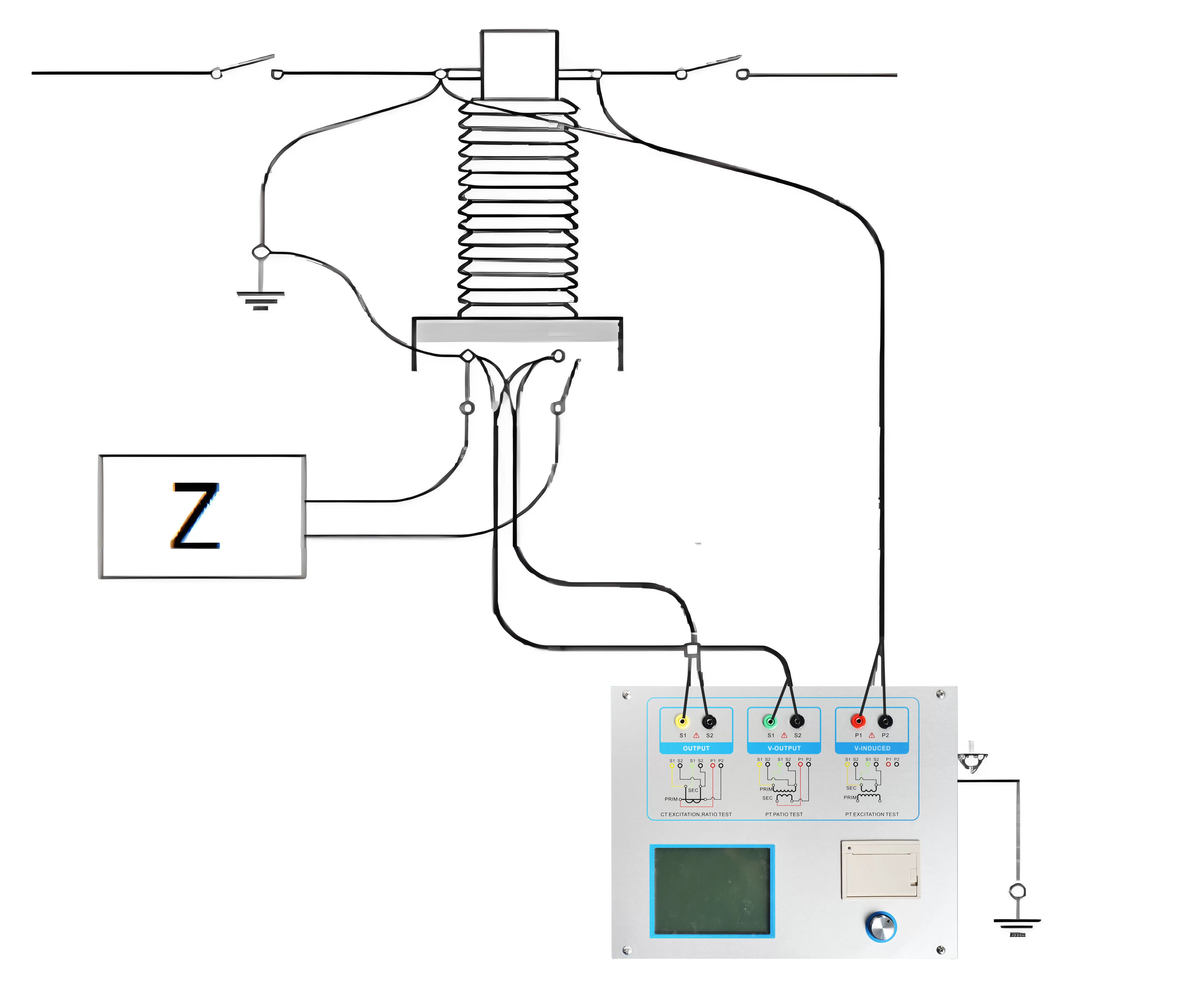
Figure D.1 Typical Connection
[1] JYH-C in the triangle connection transformer CT test conducted on the connection mode as shown in Figure D.2.
![]()
Figure D.2 CTA-1000C in the triangle on the transformer connection when the connection mode test
[2]CTA-1000C for transformer testing casing CT Connection shown in Figure D.3.
Attention: H1 terminal must be disconnected first. Otherwise, if one took the short side, the CTA-1000C cannot obtain the correct result.
![]()
Figure D.3 CTA-1000C on the transformer bushing testing at the time of CT Connection
[3]CTA-1000C in the GIS (SF6) switch on the wiring of the CT test mode as shown in Figure D.4. NOTE: Disconnect all connected with the bus switch, grounding switch closed.
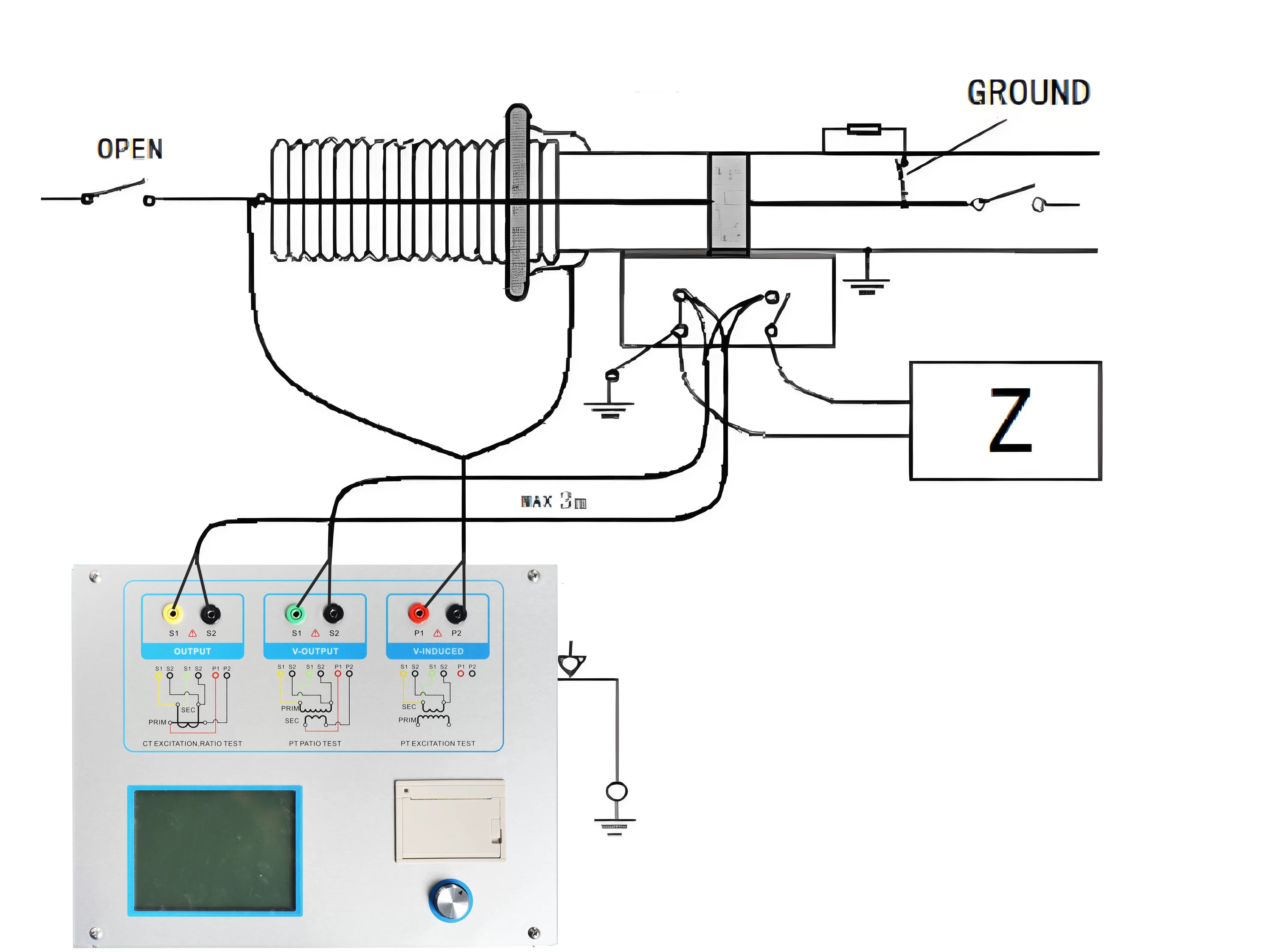
Figure D.4 CTA-1000C on GIS (SF6) switch on the test at the time of CT Connection
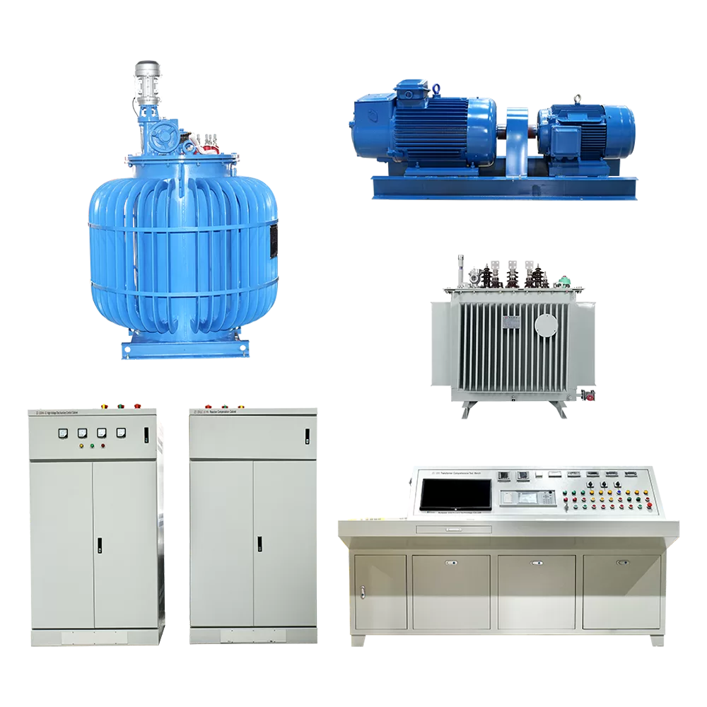
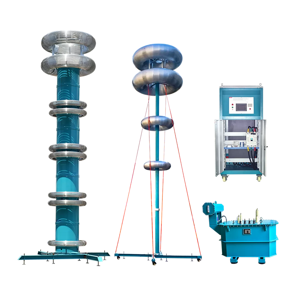
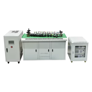
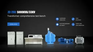
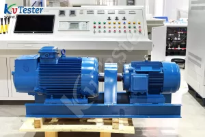
Related Products
Lasted News
-
 2026-07-08Top PT Tester For Sale – Your Best 2026 Pick
 -
 2026-07-08Smart CT Analyzer: Functions, Testing & Top Rated Models
 -
 2026-07-07CT Analyzer Price 2026 | Scenario-Based Buying Guide
 -
 2026-07-07Transformer Testing Equipment List: Full Factory & Field Guide [2026]
 -
 2026-07-07Compact Transformer Tester: Portable Test Solution