What Are the Core Functions of a Relay Protection Tester?
The relay protection tester is an indispensable piece of equipment in power system testing; its core functions are designed to comprehensively verify the operational characteristics and reliability of relay protection devices under various operating conditions. The following is a detailed summary of its core functions:
1. Standard Electrical Quantity Output Functions
① High-Precision Signal Generation:
Capable of outputting high-precision AC voltage (e.g., 0–250V), AC current (e.g., 0–150A), DC voltage (e.g., 0–300V), and DC current (e.g., 0–20A) signals, thereby meeting the input requirements of various types of relay protection devices (such as overcurrent protection and voltage protection).
② Wide-Range Adjustment:
Supports the independent adjustment of the magnitude, phase, and frequency of voltage and current signals, covering the full range of electrical quantities encountered during both normal power system operation and fault conditions.
2. Phase and Frequency Adjustment Functions
① Precise Phase Control:
Allows for the adjustment of the phase difference between voltage and current (0°–360°), which is used to test the operational logic of directional protection schemes (such as power direction relays and impedance relays).
② Dynamic Frequency Simulation:
Supports frequency adjustment within the range of 45 Hz to 55 Hz, simulating system frequency fluctuations (such as those involved in low-frequency load shedding and high-frequency protection) to verify the protection device’s ability to respond to frequency changes.
3. Fault Simulation Functions
① Reproduction of Multiple Fault Types:
Simulates various fault types—including three-phase short circuits, two-phase short circuits, single-phase-to-ground short circuits, and two-phase-to-ground short circuits—as well as abnormal operating states such as power oscillations and overloads, thereby comprehensively verifying the operational characteristics of the protection device.
② Adjustable Fault Parameters:
Allows for the configuration of parameters such as fault duration, transition resistance, and initial fault angle to simulate protection behavior under diverse fault scenarios.
4. Harmonic and Transient Signal Simulation
① Harmonic Superposition Output:
Supports the superposition of harmonics ranging from the 1st to the 20th order, with a resolution of ≤1 mHz; this function is used to test the protection device’s tolerance to harmonics (e.g., in transformer differential protection schemes, where harmonic interference must be filtered out).
② Reproduction of Transient Processes:
Simulates the transient processes that occur at the instant a fault strikes (such as sudden current changes or voltage dips) to verify the protection device’s rapid-response performance.
5. Automated Testing Capabilities
① Test Sequence Editing:
Supports user-defined test steps, automatically executing processes such as parameter configuration, fault triggering, and result recording to enhance testing efficiency.
② State Sequence Testing:
Simulates the entire lifecycle of a power system—from normal operation through fault occurrence to fault clearance—to verify the timing coordination capabilities of protection devices.
③ GPS-Synchronized Triggering:
Achieves synchronized triggering across multiple test units via GPS time synchronization, suitable for verifying line longitudinal protection schemes (e.g., differential protection).
6. Data Analysis and Report Generation
① Waveform Recording and Playback:
Records voltage and current waveforms in real-time during the testing process; supports data export in Comtrade format for subsequent analysis.
② Phasor Diagram Display:
Visualizes the phase relationships between voltage and current via phasor diagrams, enabling intuitive verification of the protection device’s operational logic.
③ Automated Report Generation:
Automatically generates test reports based on test results—including parameters such as pickup values, operating times, and dropout times—with support for printing or exporting in PDF/Excel formats.
7. Digital Protection Testing Support
① IEC 61850 Protocol Compatibility:
Supports the transmission and reception of GOOSE (Generic Object-Oriented Substation Events) and SV (Sampled Values) messages, enabling the simulation of digital protection devices (e.g., Merging Units, Intelligent Electronic Devices) within smart substations.
② Optical Digital Interface:
Equipped with fiber-optic interfaces to communicate directly with digital protection devices, verifying their message processing capabilities and operational timing.
8. Expansion Capabilities and Interfaces
① External Expansion Modules:
Supports the connection of external devices—such as power amplifiers and high-precision sensors—to enhance output capacity or measurement accuracy.
② Multi-Unit Parallel Operation:
Enables the parallel operation of multiple test units via communication interfaces to simulate complex fault scenarios within large-scale power systems.
③ Remote Control and Monitoring:
Supports remote operation of the test unit via a PC or mobile terminal, facilitating unattended testing.
9. Portability and User-Centric Design
① Lightweight Design:
Features a portable chassis (weighing <20 kg) with a built-in lithium battery, making it ideal for on-site maintenance and commissioning tasks.
② Touchscreen Operation:
Equipped with a large-format touchscreen display to simplify parameter configuration and streamline the testing workflow. ③ High Protection Rating:
Meets or exceeds the IP54 protection standard, making it suitable for harsh environments such as outdoor settings and humid conditions.
10. Application Scenarios
① Line Protection Testing: Simulates phase-to-phase short-circuit faults to verify the operating impedance and operating time of distance protection schemes.
② Transformer Protection Testing: Simulates inrush currents through harmonic superposition to verify the restraining characteristics of differential protection schemes.
③ Busbar Protection Testing: Simulates busbar faults to verify the speed and selectivity of busbar differential protection schemes.
④ Intelligent Substation Testing: Triggers protection operations via GOOSE messages to verify the communication reliability of digital protection systems.

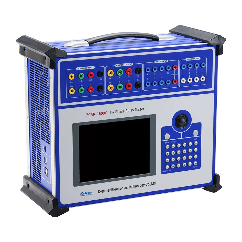
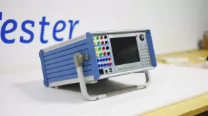
ZCAR-1600 microcomputer relay protection tester adopts high performance industrial PC as the control microcomputer and Windows operating system can be run on it directly.The whole process of the test and the test results are displayed on the liquid crystal display screen. English interface, Clear, intuitive and convenient.
ZCAR-1600 microcomputer relay protection tester is an important test tool to ensure the safety and reliability of power system operation.With the rapid development of computer technology, microelectronics technology and power electronics technology, it is an inevitable trend to launch new high performance relay protection test equipment by applying the latest technical achievements. ZCAR-1600 microcomputer relay protection tester is developed based on the standards of Technical conditions of microcomputer relay protection test device which was published by electric power department originally, referenced and summarized development and production experience, adopted modern latest new digital technology, high precision electronic parts, micro system with new circuits and new structure.It Can independently complete test of microcomputer protection, relay protection, excitation, measurement, fault recording and other professional fields tests, widely used in electric power, petrochemical, metallurgy, railway, aviation, military and other industries of scientific research, production and electrical test site.
Related Products
Lasted News
-
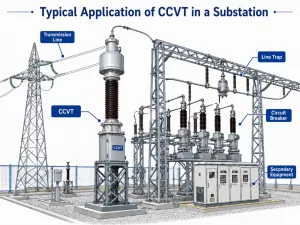 2026-06-08Review of Research and Application of Coupling Capacitor Voltage Transformers (CCVTs)
 -
 2026-06-05Electrical Insulation Testing Solution
 -
 2026-06-05Why Are DC Withstand Leaks Critical in Transformer Testing?
 -
 2026-06-04What is a Relay Protection Tester, and Why Do We Need It?
 -
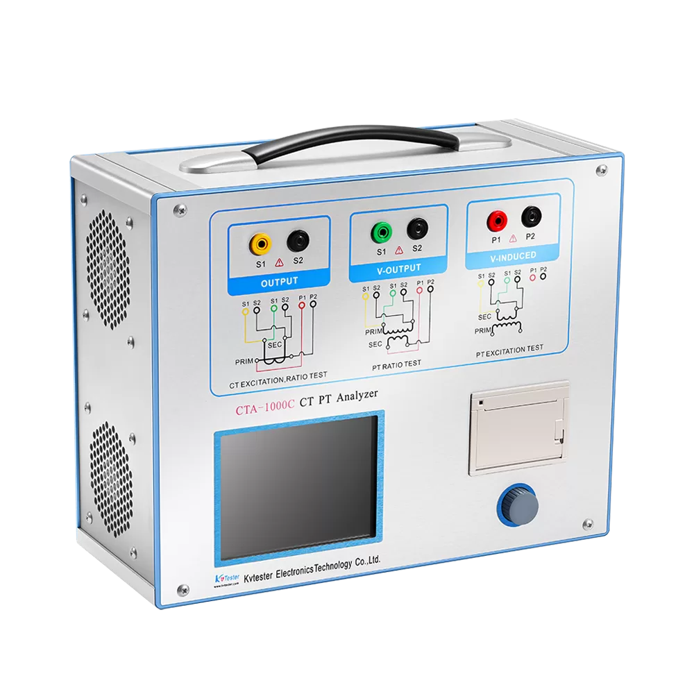
 2026-06-04How to Test CT and PT?