Classification and Selection Methods for Relay Protection Testers
1. Classification: Categorized by Function and Application Scenario
Based on the number of output channels, application scenarios, and technical characteristics, relay protection testers can be classified into the following four categories:
① Single-Phase Relay Protection Testers
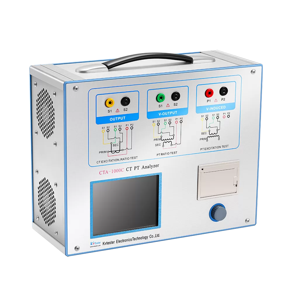
a. Applicable Scenarios: Low-voltage distribution networks (35kV and below), such as for the verification of single-phase equipment or the testing of current transformer (CT) volt-ampere characteristics.
b. Functional Features:
Supports only single-phase current/voltage output (e.g., 0–150A current, 0–250V voltage). Features simple operation and a compact size (weight ≤ 20kg), making it suitable for portable field use.
c. Typical Applications: Testing overcurrent and ground fault protection relays, or current transformers rated at 10kV and below.
② Three-Phase Relay Protection Testers
a. Applicable Scenarios: Medium-voltage distribution networks (10kV–35kV), such as for the verification of transformer differential protection and automatic transfer switch (ATS) devices.
b. Functional Features: Supports simultaneous three-phase current/voltage output (e.g., 3 × 120V voltage, 3 × 40A current). Capable of simulating three-phase faults (e.g., phase-to-phase short circuits) to verify the operational logic of protection devices.
c. Typical Applications: Line protection and busbar protection testing; supports harmonic superposition functions (1st through 20th harmonics).
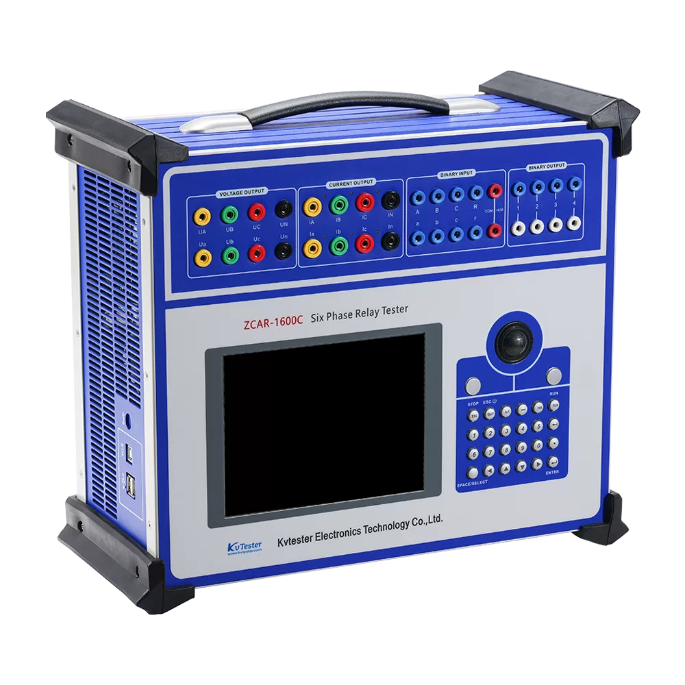
③ Six-Phase Relay Protection Testers
a. Applicable Scenarios: High-voltage (HV) and ultra-high-voltage (UHV) systems (110kV and above), such as for the verification of protection devices in intelligent substations.
b. Functional Features: Supports independent six-phase voltage/current output; compatible with the IEC 61850 protocol; supports the testing of digital protection systems (e.g., merging units, intelligent terminals). Features GPS synchronization capabilities (error ≤ 50μs), making it suitable for the verification of line longitudinal protection schemes.
c. Typical Applications: UHV DC transmission projects and protection testing for new energy power stations (e.g., wind farms, photovoltaic plants).
④ Optical-Digital Relay Protection Testers
a. Applicable Scenarios: Testing of digital protection devices within intelligent substations.
b. Functional Features: Supports the transmission of sampled values in accordance with the IEC 61850-9-2 standard, simulating the digital signals generated by merging units. Capable of verifying the SV (Sampled Values) and GOOSE (Generic Object-Oriented Substation Events) message processing capabilities of protection devices.
2. Selection Methodology: Four Core Principles
① Match Voltage Level with Protection Type
Low-Voltage Distribution Networks (0.4 kV – 10 kV): Prioritize single-phase or simplified three-phase testers; these are sufficient to meet the verification requirements for overcurrent and ground fault protection.
Medium-Voltage Distribution Networks (10 kV – 35 kV): Select standard three-phase testers that support functions such as transformer differential protection and automatic transfer schemes (ATS).
High-Voltage / Ultra-High-Voltage Systems (110 kV and above): Mandate the selection of six-phase (or multi-phase) high-precision testers that are compliant with the IEC 61850 protocol and support digital protection verification.
Output Accuracy and Capacity: Must meet core parameter requirements.
② Accuracy:
Voltage/Current Output Error: ≤ 0.2% (required for high-voltage systems); for standard distribution networks, this requirement may be relaxed to ≤ 0.5%.
Phase Accuracy: ≤ ± 0.5°; Time Accuracy: ≤ 0.1 ms—ensuring the precise timing of protection device operations.
Capacity:
Current Output Peak: Must be capable of covering the maximum operating current of the protection device (e.g., differential protection testing may require a short-duration output exceeding 200 A).
Voltage Output: ≥ 130 V; Voltage Drop under Load: ≤ 2% (at a power factor of 0.8).
③ Functional Extensibility: Supporting Complex Testing Requirements
Harmonic Simulation: Must support the superposition of 1st through 20th order harmonics, with a resolution of ≤ 1 mHz, to verify the protection device’s harmonic immunity.
Fault Waveform Playback: Capable of importing fault data in Comtrade format to reproduce actual fault waveforms.
Automated Testing: Supports automatic scanning of protection settings and automated test report generation, thereby enhancing testing efficiency.
GPS Synchronization: Applicable for the verification of line longitudinal protection schemes, ensuring data synchronization across multiple terminals.
④ Portability and User Experience: Adapting to Field Environments
For Field Maintenance: Prioritize portable models (weight < 20 kg) featuring built-in lithium batteries, touchscreen interfaces, and support for exporting test reports via USB flash drive.
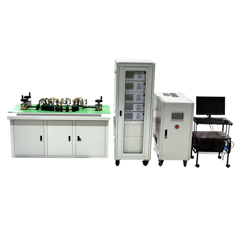
For Laboratory Use: Tabletop models are a suitable choice, emphasizing high precision and multi-channel capabilities, with the option to connect to an external computer for complex test programming. Protection Rating: For harsh environments (such as outdoors or wet locations), equipment with a protection rating of IP54 or higher should be selected.
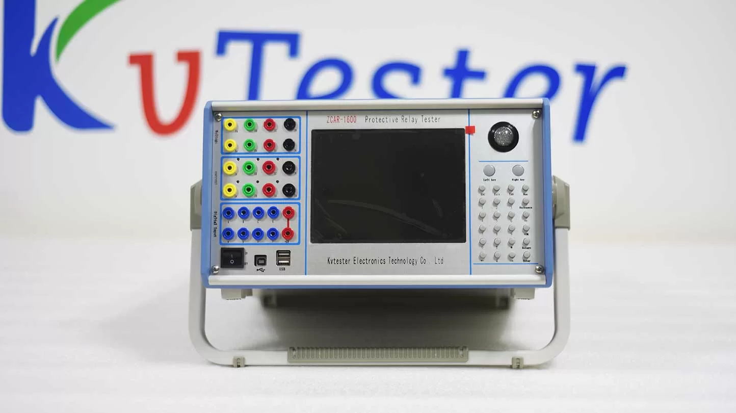
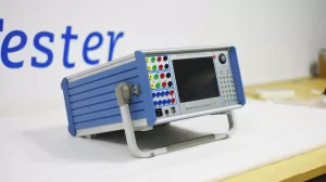
ZCAR-1600 microcomputer relay protection tester adopts high performance industrial PC as the control microcomputer and Windows operating system can be run on it directly.The whole process of the test and the test results are displayed on the liquid crystal display screen. English interface, Clear, intuitive and convenient.
ZCAR-1600 microcomputer relay protection tester is an important test tool to ensure the safety and reliability of power system operation.With the rapid development of computer technology, microelectronics technology and power electronics technology, it is an inevitable trend to launch new high performance relay protection test equipment by applying the latest technical achievements. ZCAR-1600 microcomputer relay protection tester is developed based on the standards of Technical conditions of microcomputer relay protection test device which was published by electric power department originally, referenced and summarized development and production experience, adopted modern latest new digital technology, high precision electronic parts, micro system with new circuits and new structure.It Can independently complete test of microcomputer protection, relay protection, excitation, measurement, fault recording and other professional fields tests, widely used in electric power, petrochemical, metallurgy, railway, aviation, military and other industries of scientific research, production and electrical test site.
Related Products
Lasted News
-
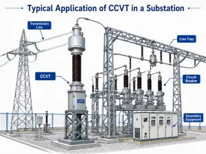 2026-06-08Review of Research and Application of Coupling Capacitor Voltage Transformers (CCVTs)
 -
 2026-06-05Electrical Insulation Testing Solution
 -
 2026-06-05Why Are DC Withstand Leaks Critical in Transformer Testing?
 -
 2026-06-04What is a Relay Protection Tester, and Why Do We Need It?
 -
 2026-06-04How to Test CT and PT?