
Home » News » Company News
PT Tester With Maintenance Service: Procurement Guide
Choosing a PT tester can feel straightforward at first: compare a few specifications, select a model, and place the order. In actual power testing work, the decision affects much more. The tester must suit the voltage transformers your team handles, support the required test procedures, produce traceable results, and remain available when a commissioning or maintenance project is underway.
For utilities, transformer manufacturers, testing laboratories, and renewable-energy contractors, maintenance support is part of the equipment decision from the beginning. This guide explains how to select a PT tester and a maintenance arrangement that fit the daily requirements of your power testing work.
Choosing a PT Tester With Maintenance Service
A PT tester may be used for electromagnetic voltage transformers (VT/PT), capacitive voltage transformers (CVT), or capacitive coupled voltage transformers (CCVT). These applications do not always require the same test functions, output capability, wiring procedure, or accuracy range.
Before comparing equipment, confirm the transformer types and work stages your team must cover:
- Factory routine testing and outgoing quality inspection
- Substation commissioning and acceptance testing
- Periodic preventive maintenance
- Accuracy verification for metering and protection circuits
- Troubleshooting after abnormal measurement, protection, or wiring results
- Wind, solar, energy-storage, and grid-connection project commissioning
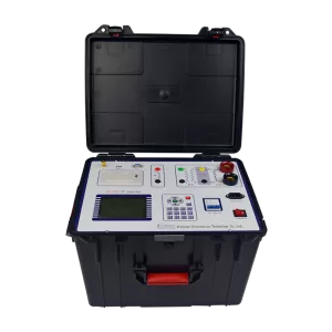
For teams that need both CT and PT functions in one field instrument, the CTA-1000C CT/PT Analyzer supports ratio, phase, polarity, winding resistance, excitation, and burden measurement. Its PT ratio range is 1 to 40,000, and its burden measurement range is 0 to 1,000 VA. This configuration can suit service teams that need to handle several instrument-transformer test tasks without carrying separate devices for each routine check.
Define the Test Functions Before Reviewing Specifications
For VT, CVT, and CCVT work, common requirements include:
- Voltage ratio measurement
- Polarity verification
- Ratio error and phase-angle error analysis
- Secondary winding DC resistance measurement
- Excitation or magnetization characteristic testing
- Secondary burden measurement
- CVT induction-ratio testing
- Test-record storage, printing, and result traceability
A dedicated voltage transformer analyzer can combine these tasks in one testing process. For VT, CVT, and CCVT applications, the PTA-2000C performs independent secondary-winding ratio measurement, ratio and phase-angle accuracy analysis at different voltages and burdens, secondary winding resistance measurement, excitation-characteristic testing, and secondary burden measurement.
For projects involving both electromagnetic and capacitive voltage transformers, confirm whether the selected tester can complete the required CVT sequence. A typical CVT workflow includes ratio testing, induction-ratio testing, resistance testing, excitation testing, error testing, and burden testing. This helps prevent a situation where an instrument completes a basic VT ratio test but cannot support the full CVT commissioning or verification process.
Confirm Applicable Standards
Testing requirements are often set by utility specifications, tender documents, export-market requirements, laboratory procedures, or manufacturing quality-control rules. The selected instrument should match the standards required for the project and the transformer type being tested.
For voltage-transformer applications, common standards include:
- IEC 60042-2 for VT
- IEC 60044-5 for CVT/CCVT
- IEC 61869-3 for VT
- IEC 61869-5 for CVT/CCVT
- IEEE C57.13 for conventional transformers
- ANSI C93.1 for CVT/CCVT
The required standard also affects parameter configuration. Before testing, the operator may need to set the transformer class, rated primary voltage, rated secondary voltage, rated burden, power factor, frequency, and voltage factor. These settings determine how measurement results are evaluated and recorded.
When sending an RFQ, include the following information:
- Transformer type: VT/PT, CVT, or CCVT
- Metering or protection winding classification
- Rated primary and secondary voltage
- Rated burden and power factor
- Required test standard
- Local system frequency: 50 Hz or 60 Hz
- Required testing voltage level and expected ratio range
- Required report format and data-retention period
Assess Field Use, Safety, and Data Handling
A tester can meet laboratory specifications but still be difficult to use in a project environment. Power-system testing teams often work during outage windows, in substations, in transformer factories, or at renewable-energy sites where equipment access, weather, transport, grounding, and test preparation affect productivity.
Evaluate practical factors such as:
- Total equipment weight, including cables and accessories
- Carrying case and vibration protection
- Display visibility for outdoor work
- Operating temperature and humidity limits
- Input power compatibility
- Test-lead labeling and wiring guidance
- Data-storage capacity and result-printing options
- Error prompts and troubleshooting support
- Availability of English manuals, wiring diagrams, and technical training
Guided test procedures can simplify field work by helping operators follow the correct sequence and identify external-wiring, ratio, or polarity issues before the test is completed. Test records should retain the selected standard, transformer type, winding class, serial number, and test time so teams can review results during maintenance planning, factory inspection, or customer acceptance.
Safety should be part of the technical evaluation, not treated as an afterthought. Before PT testing, fully disconnect the primary side from the power supply, establish reliable grounding, disconnect applicable secondary loads, and protect against nearby live parts. Do not change wiring while high-voltage output is active.
Evaluate Lifecycle Maintenance Service
A PT tester with a low purchase price may become expensive if it cannot be repaired promptly, calibrated on schedule, or supported with replacement test leads and technical guidance. Lifecycle maintenance service should therefore be reviewed during supplier evaluation and written into the procurement agreement where required.
A practical service plan should clarify:
- Warranty duration and covered components
- Repair process and technical-support contact method
- Remote troubleshooting availability
- Estimated response and repair times
- Availability of replacement cables, connectors, fuses, accessories, and other service parts
- Software or firmware update arrangements
- Calibration support and calibration documentation
- Operator training and refresher training
- Paid maintenance options after the warranty period
- International shipping, packaging, and return-repair arrangements
Maintenance should be performed by qualified technicians. A clear service arrangement should also separate warranty support, paid repair, calibration, and spare-part supply so the buyer understands what is included at each stage of ownership.
Include Calibration and Preventive Maintenance Requirements
Calibration, preventive inspection, and correct storage help maintain confidence in test results over time. Procurement teams should request a maintenance plan before the instrument is delivered instead of waiting until it displays a fault or produces questionable readings.
A maintenance schedule can include:
- Checking test leads, terminals, clamps, and connectors for wear or damage
- Verifying protective grounding connections before testing
- Inspecting ventilation openings and keeping them unobstructed
- Reviewing instrument operation after transportation or vibration exposure
- Checking the power cord, fuse rating, and external accessories
- Recording test results, fault conditions, service dates, and calibration status
- Scheduling calibration according to internal quality procedures or project requirements
- Requesting technical support when abnormal readings, overheating, overcurrent protection, or wiring faults occur
Common diagnostic conditions can include output short-circuit overcurrent protection, overtemperature protection, boost faults, ratio-test faults, resistance-test wiring faults, and mismatches between configured and measured PT ratios. A structured service process should define how the testing team records these conditions and when to arrange technical support.
Compare Total Cost of Ownership
The lowest quotation is not always the lowest long-term procurement cost. A more useful comparison looks at the full period during which the PT tester will be used.
Total Cost of Ownership = Equipment Price + Accessories + Training + Calibration + Preventive Maintenance + Repair + Spare Parts + Logistics + Downtime Risk
Downtime can affect more than the testing department. A failed instrument may delay transformer delivery inspections, extend a substation outage, postpone a renewable-energy commissioning milestone, or require a testing contractor to return to the project location.
Before making a final decision, compare quotations using the same configuration and service assumptions:
- Does the price include test leads, grounding leads, carrying case, and printed or digital documentation?
- Is operator training included?
- Is a factory test report or calibration document provided?
- Are repair and support arrangements defined after delivery?
- Can the supplier provide spare parts for the expected service life?
- Are software updates or functional upgrades available?
- Is there a clear process for overseas customers needing remote support or return repair?
For larger orders, customized configurations, or project-critical purchases, include a Factory Acceptance Test in the purchasing plan. The FAT can verify model numbers, serial numbers, accessories, basic functions, agreed measurement ranges, data-storage functions, protection functions, reports, manuals, and packing details before shipment.
Match the Equipment to Your Workflow
Different teams use PT testers in different ways. Transformer manufacturers may focus on repeatable production testing and traceable records, while substation teams often need portable equipment for planned maintenance and outage work. Laboratories may require flexible standard selection and calibration support, and commissioning teams need equipment that fits project schedules and site conditions.
Kvtester supplies power testing equipment for transformer manufacturing, substation maintenance, electrical commissioning, and laboratory applications. Its CT/PT testing solutions can be configured around the required transformer type, test functions, operating environment, and maintenance workflow.
Substation Maintenance Teams
Substation teams usually need equipment that can be transported easily, set up efficiently, and used safely during planned outage windows. Priorities often include wiring guidance, stable field operation, clear result records, and responsive maintenance support.
Transformer and Instrument Transformer Manufacturers
Manufacturers may need repeatable production-test procedures, traceable test records, standard-based evaluation, and a defined calibration plan. If the workflow includes frequent CT/PT testing, teams may consider a portable analyzer for development and verification tasks together with automated systems for high-volume factory work.
Third-Party Testing Laboratories
Independent test providers need repeatability, traceability, report management, and flexible standard selection across different customer projects. The service agreement should address calibration records, fast troubleshooting, staff training, and spare-part support to reduce interruption to contracted testing work.
Renewable Energy EPC and O&M Teams
Solar, wind, and energy-storage projects may require PT testing during substation commissioning, grid-connection preparation, and scheduled maintenance. Buyers should prioritize the applicable voltage class, test-object coverage, transport requirements, and support arrangements for remote project locations.
Questions to Ask Before Ordering
Use the following questions when comparing PT tester manufacturers and service proposals:
- Which VT, CVT, and CCVT tests can this model complete?
- What measurement range and accuracy apply to our required voltage class and ratio range?
- Which IEC, IEEE, or ANSI standards can be configured for our application?
- Can the device test metering and protection windings?
- Does the scope include ratio, polarity, error, phase angle, resistance, excitation, and burden testing?
- What accessories are included in the standard delivery?
- How are results stored, printed, and identified by transformer serial number and test date?
- What is the warranty scope, and what happens after the warranty period?
- How are repairs, remote support, spare parts, and calibration handled in our region?
- Can the supplier provide factory-test documents, manuals, training, and FAT support before shipment?
Select a PT Tester and Service Plan Together
The right PT tester should fit the transformer types, standards, measurement tasks, and working conditions of your team. The right lifecycle service plan should support the same objective by defining maintenance, troubleshooting, repair, calibration, training, and parts availability before the equipment is delivered.
For procurement teams that need a broader selection of portable analyzers, automated systems, and related solutions, explore the CT/PT test equipment range. It includes CT/PT analyzers and CT/PT testing systems for power-system detection, maintenance, transformer manufacturing, and electrical equipment testing.
Provide your transformer type, rated voltage, ratio range, applicable standard, required test items, project location, and expected service requirements when requesting a configuration proposal. This allows the equipment scope and lifecycle maintenance arrangement to be aligned with the actual testing workflow from the beginning.
Related Products





Latest News
-
 2026-09-10Working Principle and Main Applications of Anti-Interference Dielectric Loss Testers
 -
 2026-09-10Best Smart CT Tester Manufacturers for Power System Testing
 -
 2026-09-09High Precision Transformer Testing Equipment Price & FAT Guide
 -
 2026-09-09IEC Standard CT Tester Buyer’s Guide for Utilities and Testing Companies
 -
 2026-09-09How to Use a CT Tester for Reliable Maintenance Field Testing?
