What Are the Fault Simulation Types for Relay Protection Testers?
Relay protection testers verify the operational logic and reliability of protection devices by simulating various types of faults occurring within power systems. The fault simulation types cover categories such as short circuits, ground faults, open circuits, system anomalies, and compound faults. The specific classifications and their characteristics are detailed below:
1. Short-Circuit Faults
① Three-Phase Short Circuit (Symmetrical Short Circuit)
Characteristics: The voltages and currents of all three phases drop or rise simultaneously; their magnitudes are equal, and their phase angles are mutually displaced by 120°.
Application Scenarios: Testing the operational characteristics of protection schemes—such as distance protection and differential protection—under symmetrical fault conditions.
Simulation Focus: Requires precise control over the magnitude of the short-circuit current and the duration of the fault to verify the protection device’s speed of operation and selectivity.
② Two-Phase Short Circuit (Asymmetrical Short Circuit)
Characteristics: Current increases only between two specific phases, accompanied by a voltage drop, while the third phase remains normal.
Application Scenarios: Verifying the operational logic of directional protection schemes (e.g., power direction relays).
Simulation Focus: Adjusting the phase difference between the faulted phases to verify the protection device’s ability to accurately determine the direction of the fault.
③ Single-Phase-to-Ground Short Circuit
Characteristics: The voltage of one phase drops to zero, and its current increases significantly, while the voltages of the other two phases rise (in systems with an ungrounded neutral point).
Application Scenarios: Testing the response to ground faults using schemes such as zero-sequence protection and ground distance protection.
Simulation Focus: Setting the fault transition resistance (e.g., simulating a metallic ground or a high-resistance ground) to verify the protection device’s sensitivity.
④ Two-Phase-to-Ground Short Circuit
Characteristics: Two phases ground simultaneously; the changes in current and voltage are complex and may be accompanied by zero-sequence components.
Application Scenarios: Verifying the coordinated operational capability of protection devices under compound fault conditions.
Simulation Focus: Requires simultaneous control over the ground resistance of both faulted phases and the duration of the fault.
2. Ground Faults
① Metallic Ground Fault
Characteristics: The fault transition resistance is close to zero; the fault current is large, and the voltage drop is pronounced.
Application Scenarios: Testing the protection device’s rapid response to severe ground faults.
② High-Resistance Ground Fault
Characteristics: The fault transition resistance is relatively high (e.g., several hundred ohms); the fault current is small, and voltage changes occur slowly.
Application Scenarios: Verifying the protection device’s ability to detect concealed faults (e.g., line selection in small-current grounded systems). ③ Arcing Ground Fault
Characteristics: Significant fluctuations in fault current, accompanied by high-frequency harmonics, simulating the process of an electric arc.
Application Scenarios: Testing the performance of arc-suppression coil grounding systems or arc-protection devices.
3. Open-Circuit Faults
① Single-Phase Open Circuit
Characteristics: The current in one phase drops to zero, while the currents in the other two phases may increase; voltage imbalance occurs.
Application Scenarios: Verifying open-circuit blocking functions (e.g., preventing maloperation of distance protection).
② Two-Phase Open Circuit
Characteristics: The currents in two phases drop to zero, while the current in the remaining phase may increase abnormally.
Application Scenarios: Testing the protection device’s ability to identify non-full-phase operating conditions.
4. System Abnormal Operating Conditions
① System Oscillation
Characteristics: Periodic fluctuations in voltage and current magnitudes, frequency deviation, and repeated reversals in power direction.
Application Scenarios: Testing oscillation blocking functions (e.g., preventing maloperation of distance protection during oscillations).
Simulation Key Points: Setting the oscillation period, amplitude, and initial phase angle.
② Overload
Characteristics: Current exceeds the rated value for an extended period, potentially accompanied by a rise in temperature.
Application Scenarios: Verifying the time-delay characteristics of overload protection schemes (e.g., thermal relays, inverse-time overcurrent protection).
③ Frequency Anomaly
Characteristics: System frequency deviates from the rated value (e.g., 45 Hz – 55 Hz).
Application Scenarios: Testing the operating thresholds of frequency-sensitive devices, such as low-frequency load shedding and high-frequency protection.
5. Compound Faults
① Short-Circuit + Ground Fault Combination
Characteristics: Simultaneous occurrence of a short circuit and a ground fault; complex changes in current and voltage, potentially involving zero-sequence and negative-sequence components.
Application Scenarios: Verifying the coordinated operation capability of protection devices under multiple fault conditions.
② Evolving Faults
Characteristics: The type of fault changes over time (e.g., starting as a single-phase ground fault and subsequently evolving into a phase-to-phase short circuit).
Application Scenarios: Testing the dynamic response and reclosing logic of protection devices.
6. Transient Process Simulation
① Impact of Fault Initial Angle
Characteristics: The voltage phase angle at the instant the fault occurs (e.g., 0°, 90°) influences the current waveform and the protection device’s operating time.
Application Scenarios: Verifying the sensitivity of protection devices (e.g., directional protection) to the fault’s initial angle. ② Sudden Current Changes and Voltage Sags
Characteristics: Simulates the instantaneous surge in current and abrupt drop in voltage that occur during a fault, testing the high-speed response capability of protection devices.
③ Harmonic Interference
Characteristics: Superimposes higher-order harmonics (e.g., 5th and 7th) to simulate the effects of nonlinear loads or ferroresonance.
Application Scenarios: Verifies the harmonic immunity of protection devices (e.g., the 2nd harmonic restraint function in transformer differential protection).
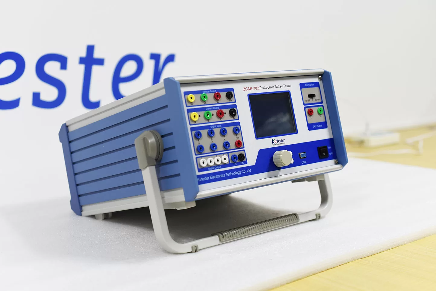
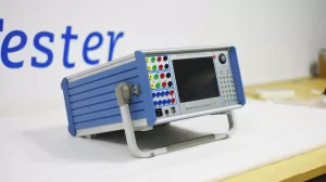
ZCAR-702C Relay protection tester In addition to the verification of various relays (such as current, voltage, inverse time limit, power direction, impedance, differential, low cycle, synchronous, frequency, DC, intermediate, time, etc.) and microprocessor-based protection, the whole group of tests can be carried out to simulate the instantaneous, permanent and conversion faults from single-phase to three-phase. It can also complete all kinds of large-scale and complex verification work with high degree of automation, automatically test and scan all kinds of protection settings, store test data in real time, display vector diagram, print reports online, etc
Related Products
Lasted News
-
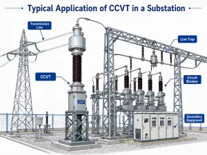 2026-06-08Review of Research and Application of Coupling Capacitor Voltage Transformers (CCVTs)
 -
 2026-06-05Electrical Insulation Testing Solution
 -
 2026-06-05Why Are DC Withstand Leaks Critical in Transformer Testing?
 -
 2026-06-04What is a Relay Protection Tester, and Why Do We Need It?
 -
 2026-06-04How to Test CT and PT?