A Must-Read Before Buying a Relay Protection Tester! How to Avoid the Pitfalls of the Three Core Parameters?
When selecting a microcomputer-based relay protection tester, to avoid the pitfalls associated with the three core parameters—accuracy, bandwidth, and output capacity—one must make a comprehensive assessment based on technical standards, actual testing verification, and functional suitability. The specific strategies are outlined below:
1. Accuracy: Beware of the “Paper Data” Trap; Focus on Hardware Configuration and Actual Verification
① Industry Standard Requirements
Voltage and current measurement accuracy must reach Class 0.2 or better (i.e., error ≤ ±0.2% of reading + 1 digit), and waveform distortion must be ≤ 0.5%. Some manufacturers claim “Class 0.1 high precision” but actually utilize 8-bit DAC chips (whereas the industry mainstream is 16-bit), resulting in output signal distortion exceeding 5%. For instance, a substation using such equipment to verify line protection encountered a current signal error of up to 3A; this led to incorrect protection setting values and nearly triggered a misoperation (unwanted tripping).
Strategies to Avoid Pitfalls
a. Contractual Constraints: Explicitly require the use of 16-bit or higher-resolution high-speed DAC chips (e.g., ADI’s AD5764) and specify core parameters such as accuracy and distortion levels.
b. On-site Verification: Connect a standard signal source to test the error within the 0–120% range of the rated current/voltage. Ensure that full-scale accuracy meets the standards, thereby avoiding situations where the device is “accurate only at the rated point but inaccurate at extreme values.”
2. Bandwidth: Focus on Dynamic Response and Harmonic Processing Capabilities; Avoid “False Bandwidth” Claims
① Industry Standard Requirements
The bandwidth must cover the typical fault frequency range of power systems (e.g., 45–550 Hz), and the waveform must remain undistorted during harmonic output. Some manufacturers claim “support for 100 kHz bandwidth” but, in reality, can only process the fundamental frequency; when outputting harmonics, the distortion levels exceed acceptable limits. For example, a power research institute testing the protection system for a 220 kV main transformer had to interrupt the experiment because the tester was unable to simulate the high-order harmonics present in the excitation inrush current.
② Strategies to Avoid Pitfalls
a. Harmonic Output Verification: Require the equipment to support the superposition of 2nd through 20th order harmonics at arbitrary amplitudes, with a frequency resolution of ≤ 1 mHz. For example, when testing the 9th harmonic (450 Hz), it is essential to ensure that the number of output points per cycle is ≥ 55 and that the waveform distortion is ≤ 0.5%.
b. Dynamic Response Testing: The response time for the current to rise from 0 to its rated value must be ≤ 100 μs to prevent response lag from causing errors exceeding 10 ms in the measurement of protection operation times.
3. Output Capacity: Clearly distinguish between “continuous output” and “short-term peak output” to avoid “inflated capacity specifications.”
① Industry Standard Requirements:
a. Current Output: Continuous output must be ≥ 40 A/phase (≥ 120 A in three-phase parallel mode), while short-term peak output (e.g., for 1–10 seconds) may reach higher values (e.g., 120 A).
b. Voltage Output: Continuous output must be ≥ 125 V/phase, with an output voltage drop of ≤ 2% under load (at a power factor of 0.8).
② Strategies for Avoiding Pitfalls:
a. Contractual Clauses: Explicitly specify the required continuous output capacity (e.g., continuous current output ≥ 40 A/phase, continuous voltage output ≥ 125 V/phase) and document parameters such as voltage drop under load and response time.
b. Practical Verification: Test the equipment’s load-bearing capability using a high-current load (e.g., a resistance box) to ensure that the output voltage and current remain stable without significant drops.
4. Comprehensive Recommendations for Avoiding Pitfalls: Base decisions on actual requirements while balancing functional capabilities with after-sales support.
① Selection Based on Application Scenario:
a. Low-Voltage Distribution Networks (0.4 kV – 10 kV): Select a single-phase or basic three-phase tester; this is sufficient for verifying overcurrent and ground fault protection.
b. Medium-Voltage Distribution Networks (10 kV – 35 kV): Select a standard three-phase tester that supports functions such as transformer differential protection and automatic transfer switching (ATS).
c. High-Voltage/Ultra-High-Voltage Systems (110 kV and above): It is mandatory to select a high-precision six-phase (or multi-phase) tester that is compatible with the IEC 61850 protocol and supports digital protection verification.
② Functional Expandability:
a. Prioritize equipment that supports harmonic simulation, fault waveform playback, and GPS-synchronized testing to ensure coverage of complex protection testing requirements. b. Software Algorithm Verification: The system must support “customizable fault sequence editing” (e.g., setting a delay for a “overcurrent → gas-actuated trip” sequence), and the waveform sampling rate must be ≥ 2000 points per cycle.
③ Safety and Reliability
Mandatory Requirement for “Triple Safety Interlock”: Zero-position closing protection, overvoltage/overcurrent protection (response time ≤ 10 ms), and an emergency stop button.
Selection of “Fully Shielded Design” Equipment: The enclosure must utilize a shielded aluminum alloy housing; signal cables must feature double-layer shielding; and the control circuitry must be physically isolated from the high-voltage output circuitry.
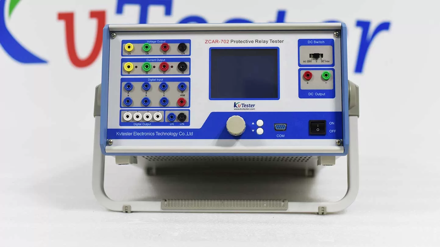
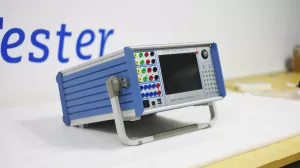
ZCAR-702C Relay protection tester In addition to the verification of various relays (such as current, voltage, inverse time limit, power direction, impedance, differential, low cycle, synchronous, frequency, DC, intermediate, time, etc.) and microprocessor-based protection, the whole group of tests can be carried out to simulate the instantaneous, permanent and conversion faults from single-phase to three-phase. It can also complete all kinds of large-scale and complex verification work with high degree of automation, automatically test and scan all kinds of protection settings, store test data in real time, display vector diagram, print reports online, etc
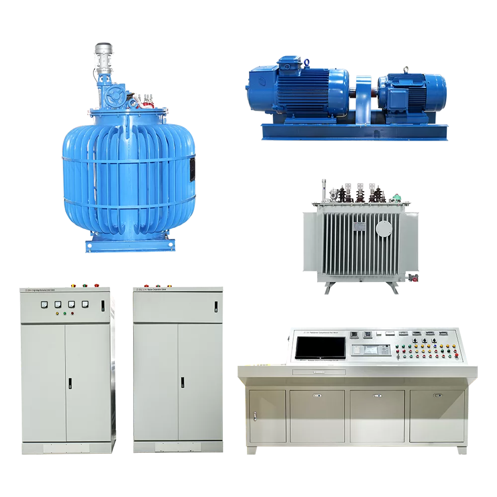
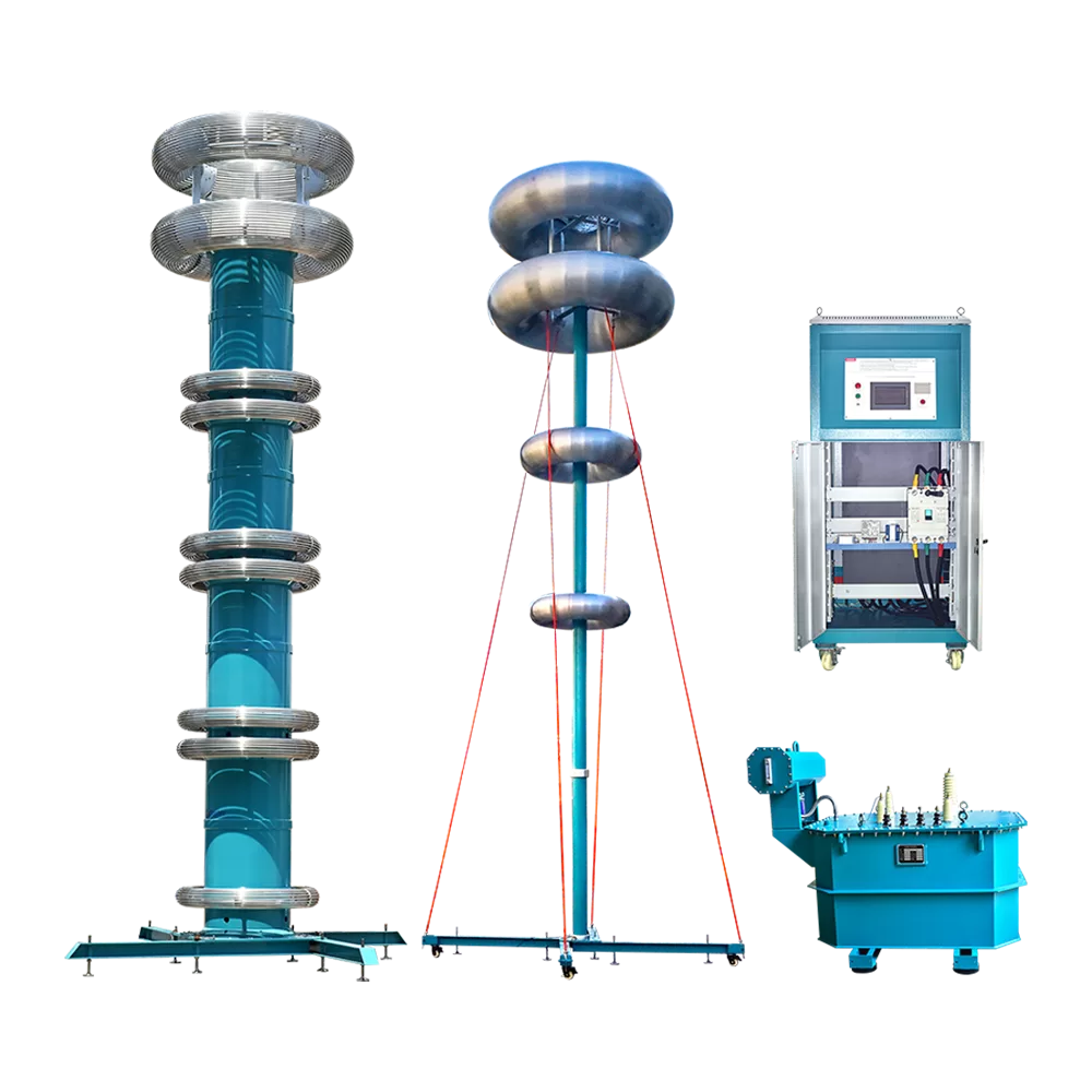
Related Products
Lasted News
-
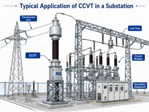 2026-06-08Review of Research and Application of Coupling Capacitor Voltage Transformers (CCVTs)
 -
 2026-06-05Electrical Insulation Testing Solution
 -
 2026-06-05Why Are DC Withstand Leaks Critical in Transformer Testing?
 -
 2026-06-04What is a Relay Protection Tester, and Why Do We Need It?
 -
 2026-06-04How to Test CT and PT?