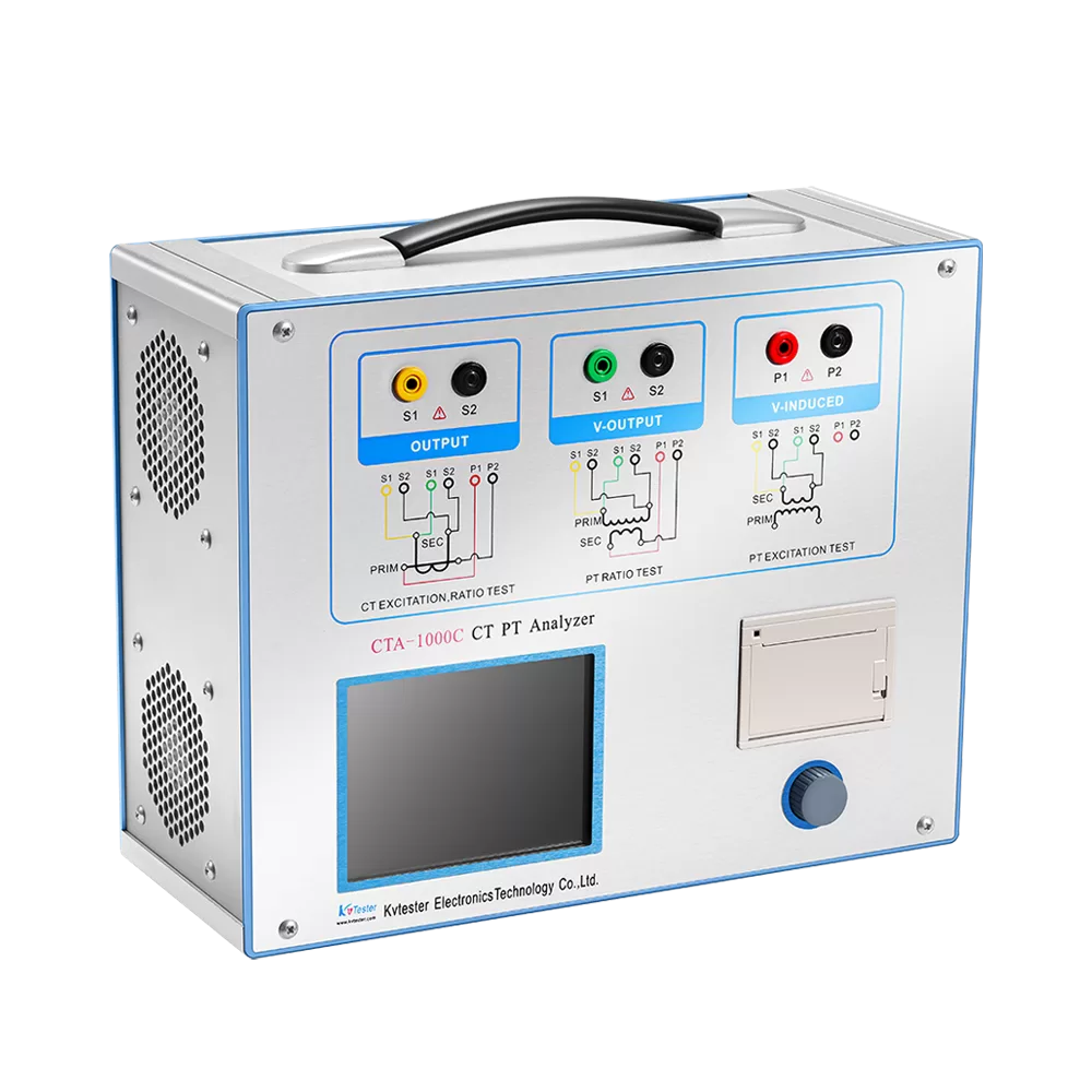
Features and Advantages
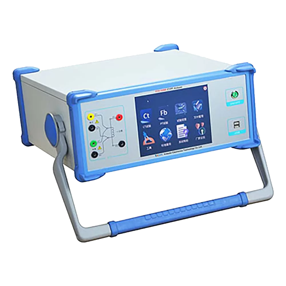
1. The instrument features a newly added testing function for dual-winding PTs (Voltage Transformers); this allows for testing without the need for an external load box and utilizes a user-friendly touchscreen interface for operation.
2. Internally, the instrument houses a multi-ratio, self-boosting standard voltage transformer with an accuracy class of 0.05. This enables the accurate verification of errors in power voltage transformers at test voltages of 1200V and 2400V.
3. When measuring electromagnetic voltage transformers, the instrument employs a simulated load technology. This technology allows for the extrapolation of load errors under both rated load and minimum load conditions; consequently, an external voltage load box is not required during the verification process for electromagnetic voltage transformers.
4. The internal voltage transformer verifier module within the instrument possesses an accuracy class of 2.
5. The instrument features an automatic sampling function for standard-specified test points, making the process of conducting routine compliance measurements extremely convenient and rapid for the user.
6. The instrument incorporates an internal power source output and automatic voltage boosting capabilities, complemented by superior safety protection features.
7. The instrument utilizes our company’s newly developed “Universal Platform” technology. This platform allows users to conveniently access useful resources—such as historical measurement data and wiring diagrams for various types of test objects—directly through the interface. It directly provides measured values, rounded values, error curves, and other data for each specific point. It automatically evaluates the measurement results, thereby further enhancing the instrument’s level of intelligence.
Parameter
- Environmental Conditions
- Equipment Parameters
- Internal Standard Voltage Transformer Parameters
- Internal Instrument Transformer Calibrator Parameters
| Environmental Conditions | |
| Temperature | 5–40°C |
| Relative Humidity | <80% (at 25°C) |
| Altitude | <2500 m |
| Power Frequency | 50 Hz ±0.5 Hz |
| Equipment Parameters | |
| Instrument Overall Error | 0.05% |
| Accuracy Class Range of Tested Voltage Transformers | 0.2, 0.5, 1 |
| Instrument Power Consumption | 100 VA |
| Instrument Output Power | 500 VA |
| Internal Standard Voltage Transformer Parameters | |
| Transformation Ratio Range | 10kV/100V, 10kV/√3 / 100V/√3 |
| 35kV/100V, 35kV/√3 / 100V/√3 | |
| 110kV/√3 / 100V/√3 | |
| 220kV/√3 / 100V/√3 | |
| Accuracy Class | 0.05% |
| Operating Voltage | 0V – 2400V |
| Output Capacity | 50VA |
| Internal Instrument Transformer Calibrator Parameters | |
| Measurement Range (Traditional Mode) | In-phase Component (%): 0.0001 – 3.0 | Resolution: 0.0001 |
| Quadrature Component (min): 0.001 – 99.9 | Resolution: 0.001 | |
| Measurement Range (Low-to-High Calibration Mode) | In-phase Component (%): 0.0001 – 200.0 | Resolution: 0.0001 |
| Quadrature Component (min): 0.001 – 999.9 | Resolution: 0.001 | |
| Admittance (mS): 0.0001 – 59.9 | Resolution: 0.0001 | |
| Basic Error | In-phase Component: △X = ± (X × 2% + Y × 2% ± 2 digits) |
| Quadrature Component: △Y = ± (X × 2% + Y × 2% ± 5 digits) | |
| “X”, “Y” — The displayed values on the instrument | |
| “5 digits” — The quantization error of the instrument | |
| Percentage Meter: Class 1 | |
| Operating Range | Voltage: (5% – 149%) Un (where Un = 100V, 150V, or 100V/√3) |
| Operating Burden | Voltage: a-to-x < 0.25 VA (at 100V) |
| Polarity Indication | During the first step of measurement in the Low-to-High Calibration Mode—provided the operating voltage exceeds 2V—if the “a” terminal of the Voltage Transformer Under Test (VTUT) is connected to the “x” terminal of the calibrator, and the “x” terminal of the VTUT is connected to the “a” terminal of the calibrator, the displayed error should read 200%, and a polarity error indication should appear. Note: During testing, if the voltage exceeds 10V and no polarity error indication appears, it indicates a malfunction within the instrument itself. Please stop the test immediately to prevent damage to the instrument. |