Features and Advantages
1. Capable of performing fully automatic measurements for three-phase three-wire, three-phase four-wire, and single-phase systems.
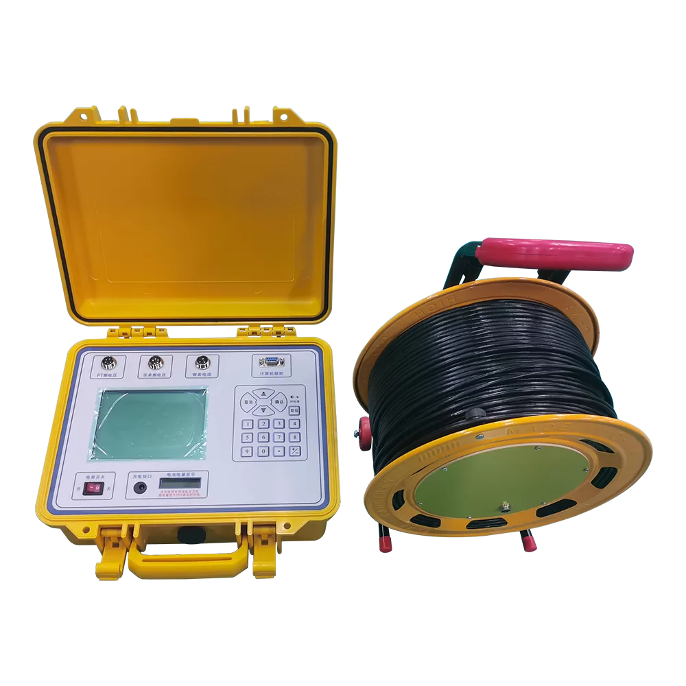
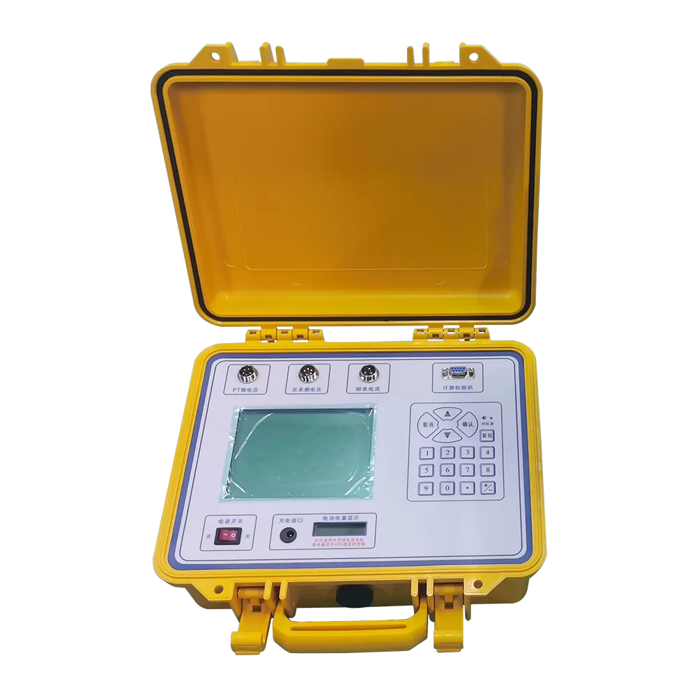
2. Housed in an engineering-grade plastic casing, which is robust and durable, effectively ensuring the safety of both the testing personnel and the system.
3. The instrument features an automatic range-switching function to ensure high measurement accuracy.
4. Employs an electronic circuit design combined with DSP technology to ensure excellent measurement stability and strong anti-interference capabilities.
5. Upon completion of measurements, the device automatically calculates all load-related parameters, facilitating customer analysis and testing.
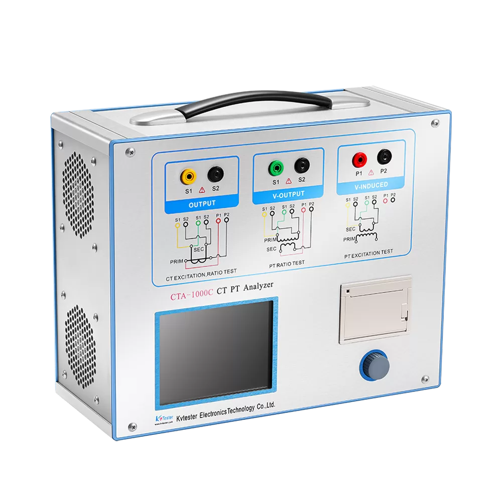
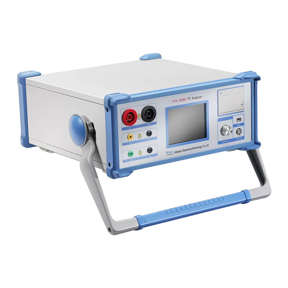
6. Features a large-screen LCD display with Chinese character prompts; all operations are guided via a Chinese-language menu. The device supports data storage with power-loss retention capabilities and allows for data browsing; it can also connect to a computer for data transmission.
7. Powered by a high-capacity 7.2V/11Ah lithium battery, which imposes no impact on the test circuit, thereby preventing the system from triggering protection mechanisms. It also enables operation in field environments where no external power supply is available.
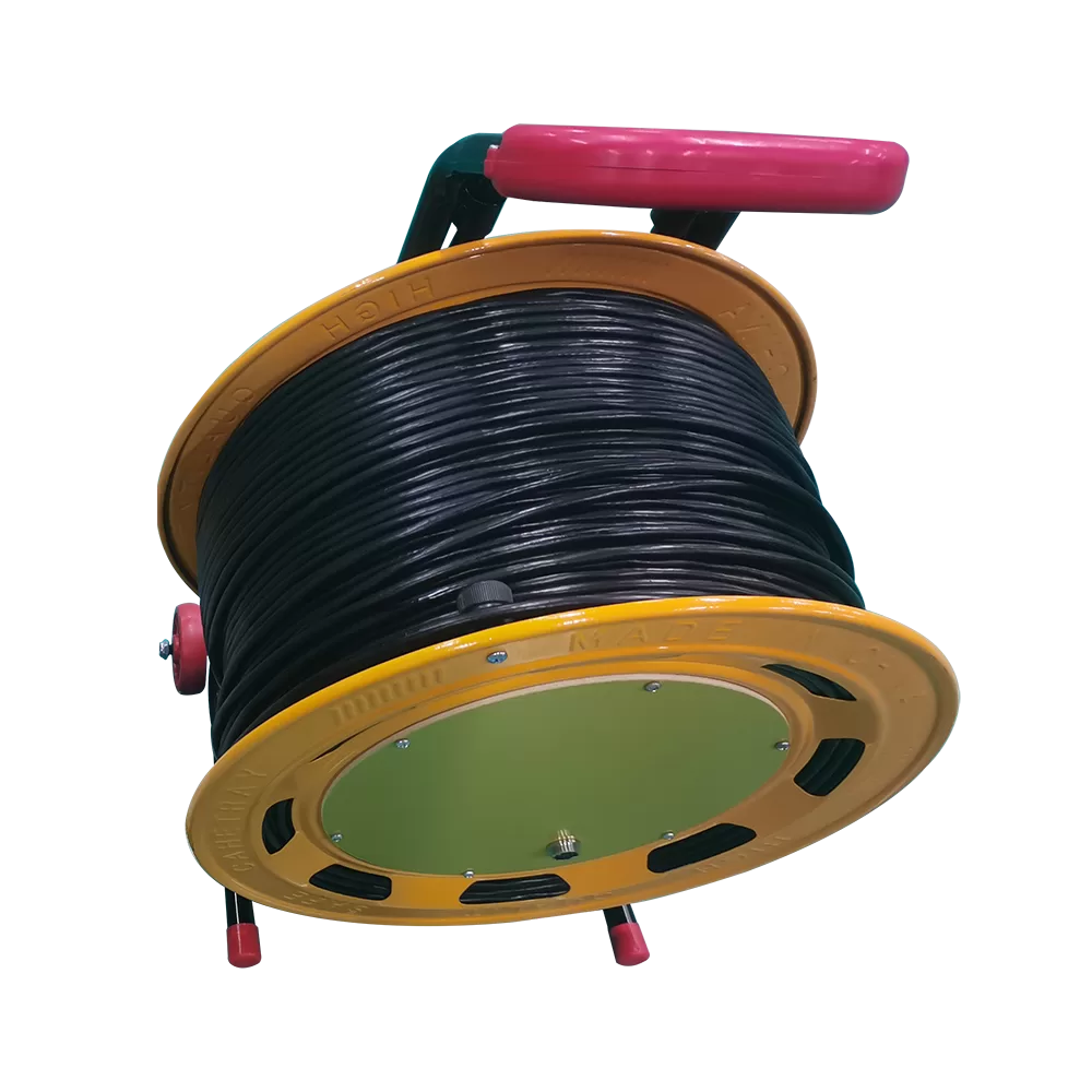
8. For load testing, a clamp-on current meter is used for current sampling, eliminating the need to disconnect the secondary circuit. This enables “hot-line” (non-interruptive) online measurements. Automatic Range Switching: During the measurement process, the device automatically adjusts its range settings based on the specific values of the test object, thereby guaranteeing both measurement accuracy and display resolution.
9. Offers an extended operating time of up to 24 hours (maximum).
10. Includes a lightweight, portable charger for convenient use; measurements can be performed using the external charger if the battery power runs low.
11. The instrument features a compact size and lightweight design.
12. Offers an extremely wide operating range for secondary-side current and voltage. At an operating current of 50mA, it can resolve resistance and reactance values as low as 1mΩ, enabling the online testing of actual loads for Class S Current Transformers with a secondary rated current of 5A. At an operating voltage of 5V, it can resolve conductance and susceptance values as low as 0.001mS.
13. Capable of storing up to 480 sets of measurement data, with data retention guaranteed for ten years even after power loss.
14. Features a large-screen display with a English-language interface and includes an RS-232 communication port.
Parameter
- Environmental Conditions
- Secondary Voltage Drop Test Parameters
- PT Secondary Burden Test Parameters
| Environmental Conditions | |
| Temperature | -10°C~40°C |
| Relative Humidity | <85% (at 25°C) |
| Altitude | <2500 m |
| External Interference | No severe vibration; no strong electromagnetic fields |
| Secondary Voltage Drop Test Parameters | |
| Measurement Range | Ratio Error: 0.001% – 19.99% |
| Phase Angle Error: 0.01’ – 599’ | |
| Resolution | Ratio Error: 0.001% |
| Phase Angle Error: 0.01’ | |
| Voltmeter Accuracy | 0.5% |
| Operating Voltage Range | 50 – 120 V |
| Instrument Basic Error | X = △ (2% × X + 2% × Y) ± 2 digits |
| Y = △ (Y × 2% + X × 2% × 34.38) ± 2 digits | |
| (where “± 2 digits” represents the instrument’s quantization error) | |
| Instrument Indication Trigger Values | Error: Ratio error > 20% or Angle error > 600’ |
| Voltage: Voltage < 2.0 V | |
| PT Secondary Burden Test Parameters | |
| Admittance Measurement Range | 0.1 mS – 50.0 mS |
| Admittance Measurement Accuracy | Secondary Voltage (50 V – 120 V) |
| X = ± (2% × X + 2% × Y) ± 2 digits | |
| Y = ± (2% × X + 2% × Y) ± 2 digits | |
| “2 digits” refers to the instrument’s quantization error | |
| Note: When the measured value is below 0.2 mS, the test voltage must be maintained above 50 V; additionally, ensure that the conductor passing through the clamp meter remains centered. Under these conditions, the instrument’s quantization error is 5 digits. | |
| Voltmeter Accuracy | 0.5% |