Features and Advantages
1.All-in-one multifunction, full test scenario coverage
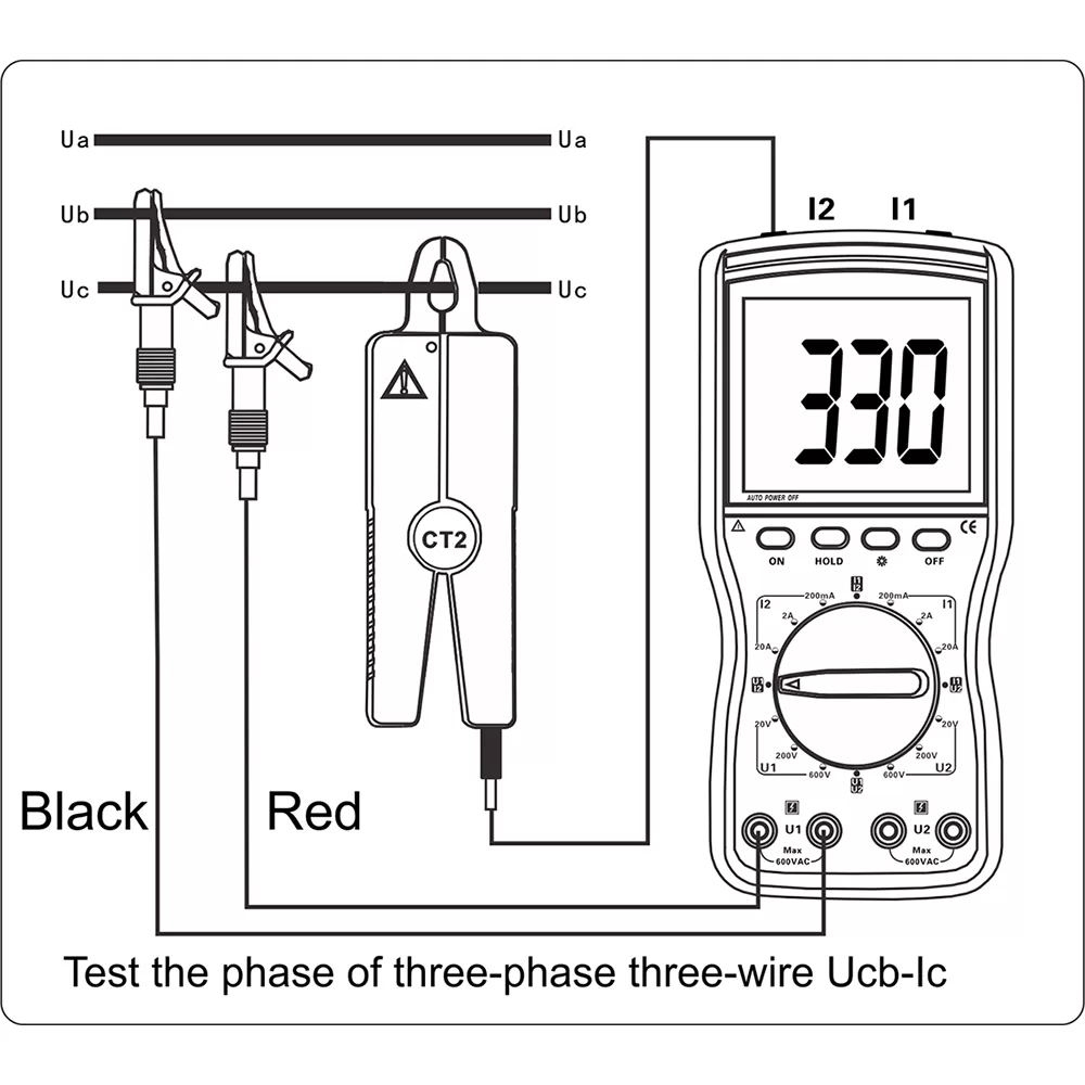
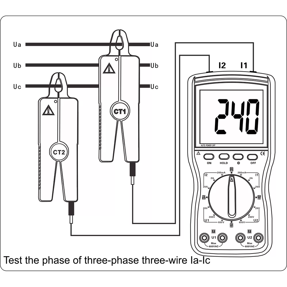
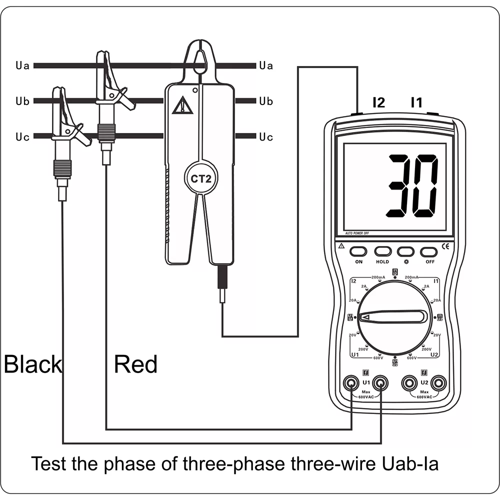
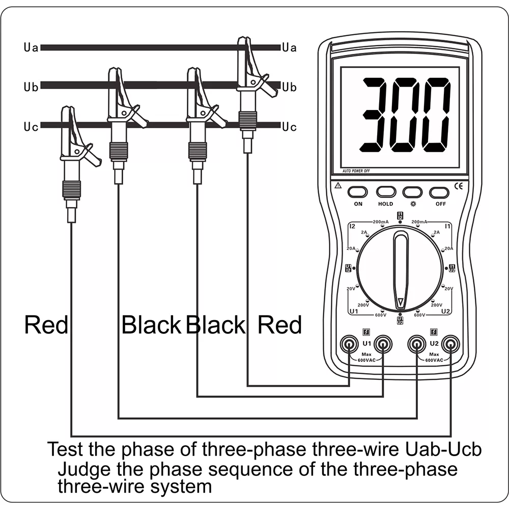
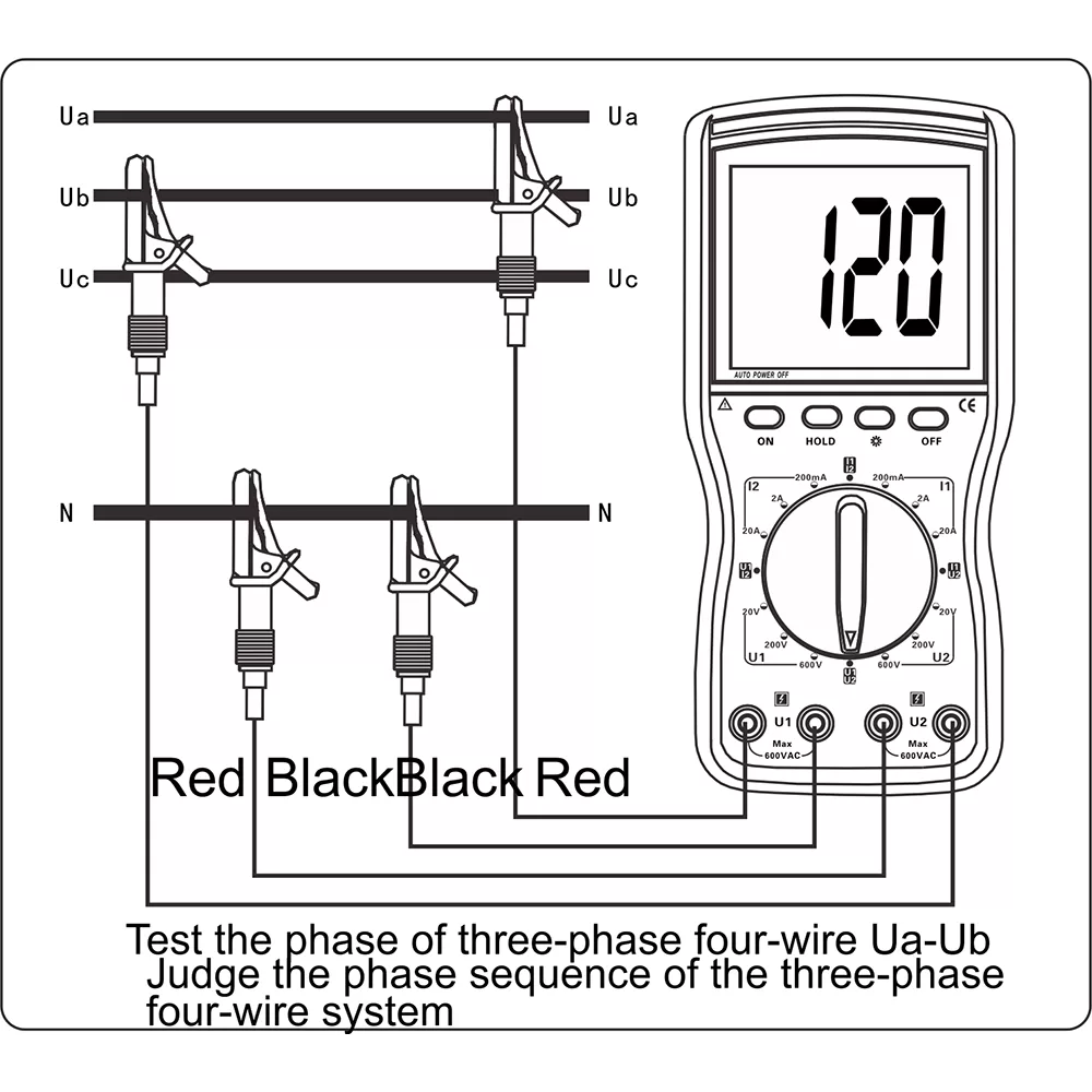
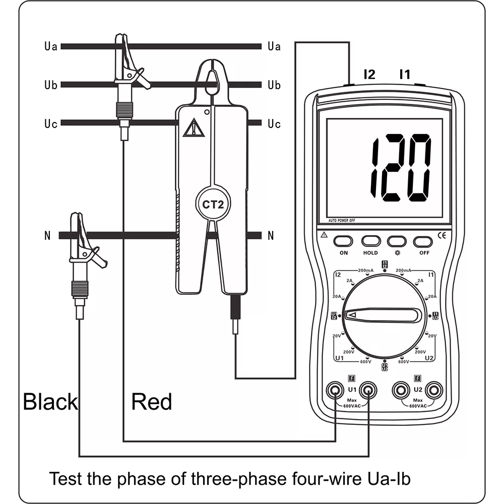
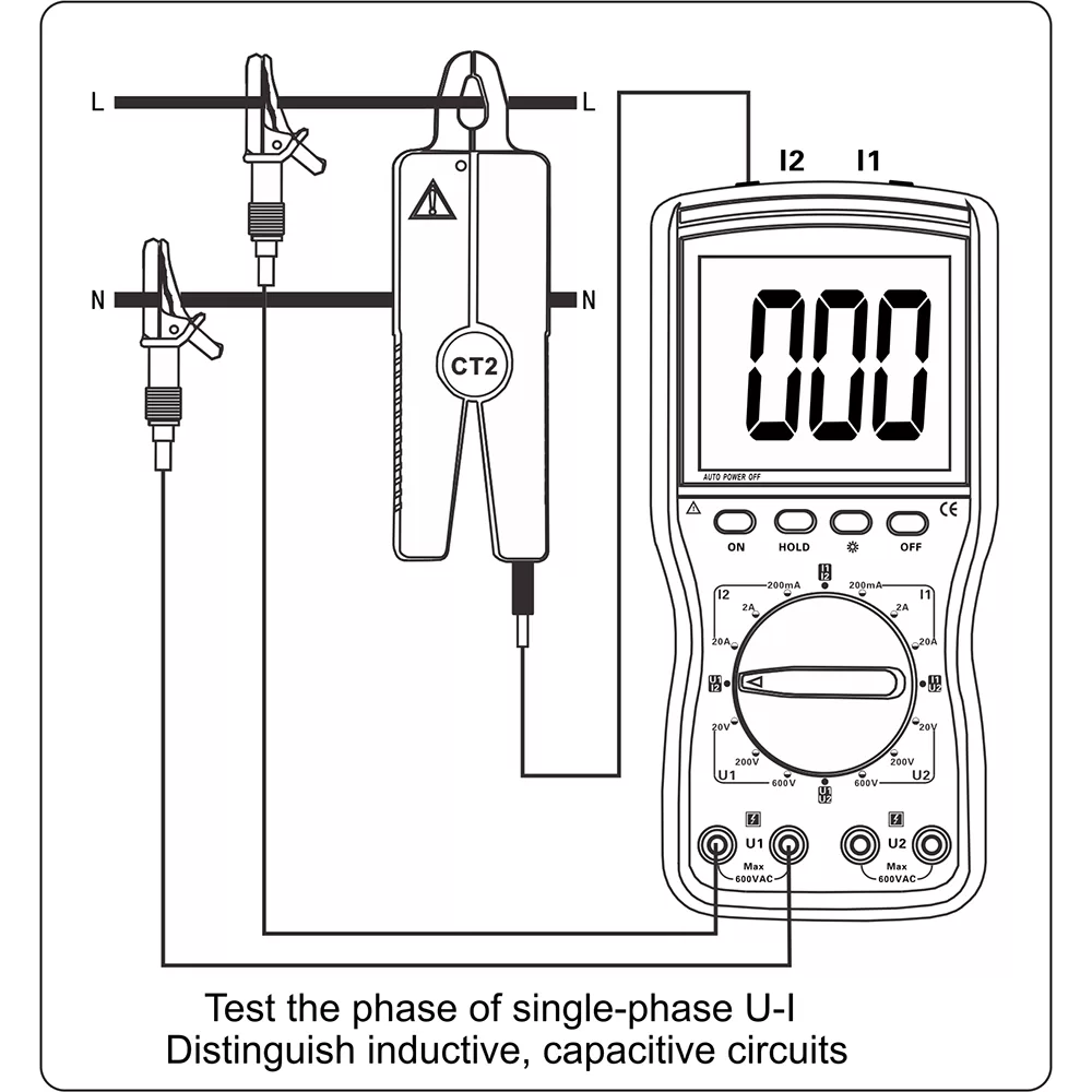
It can measure three-phase AC voltage, current, phase, frequency, phase sequence, power, power factor and more without disconnecting the tested circuit. It also identifies transformer wiring groups, inductive/capacitive circuits, inspects secondary circuits, differential protection systems and watt-hour meter wiring, suitable for power, petrochemical, metallurgy, railway and other industries.
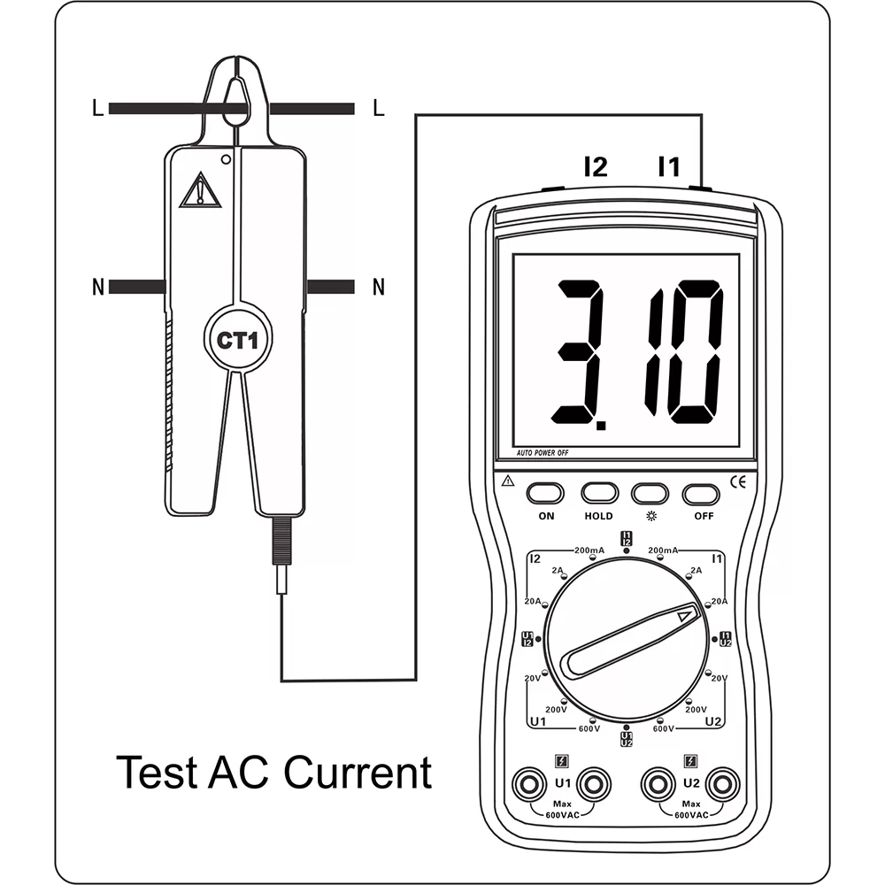
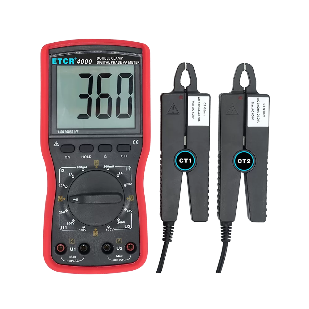
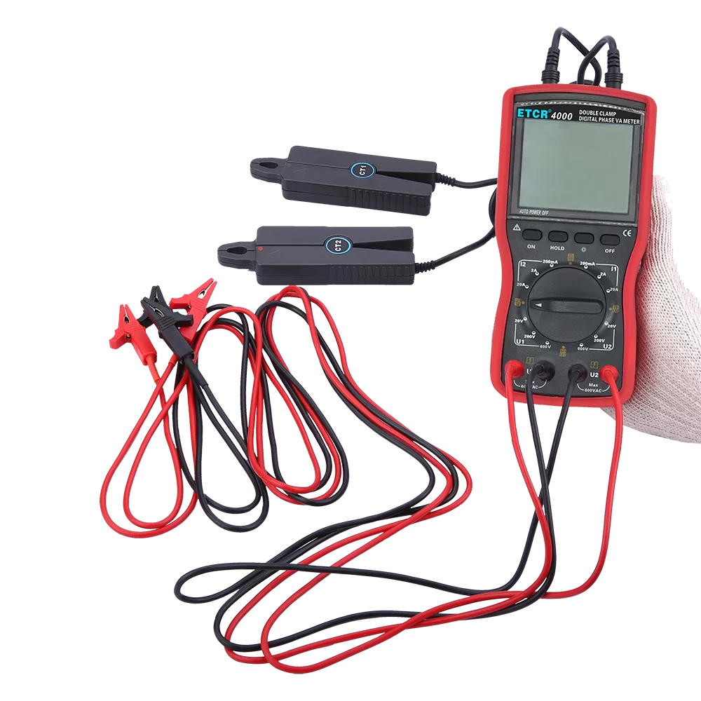
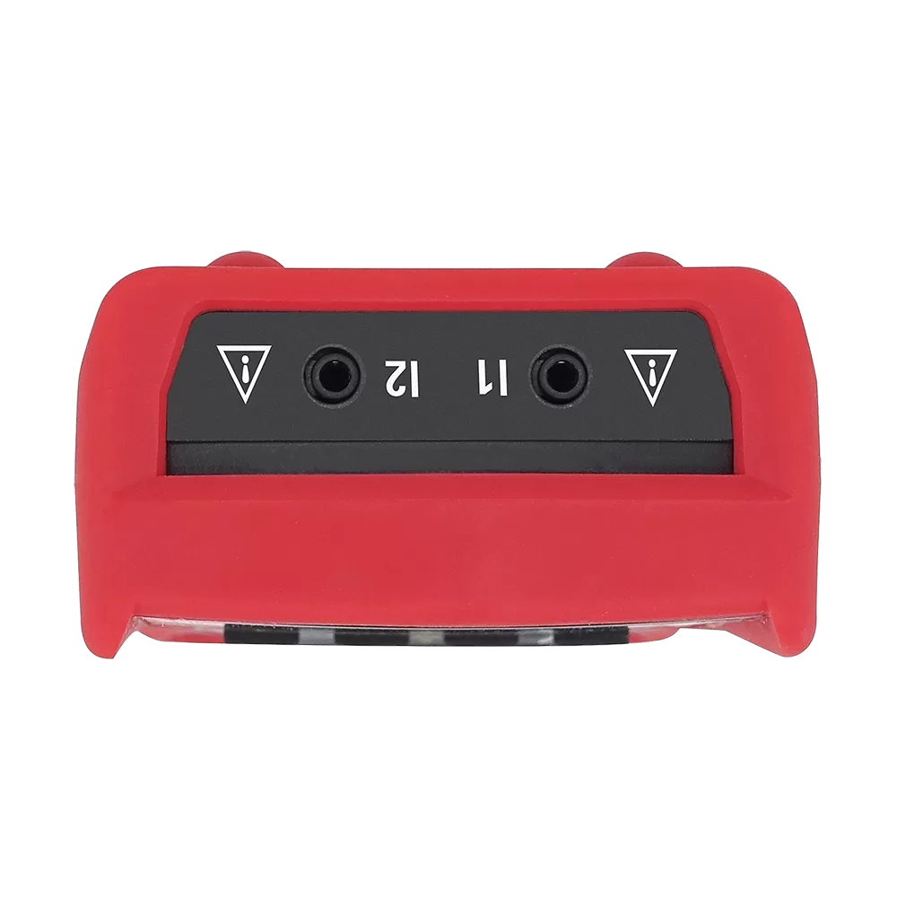
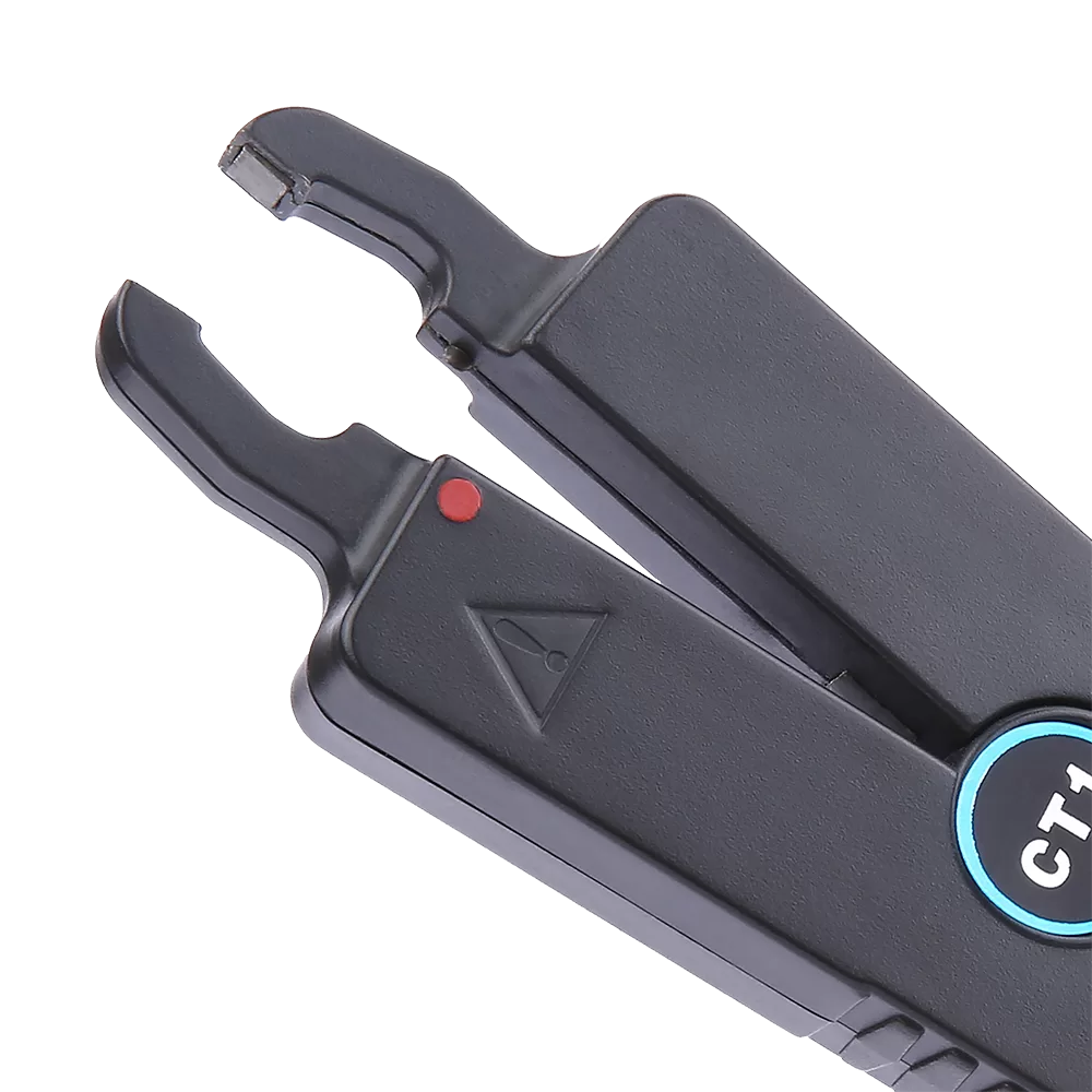
2.Dual-clamp non-contact measurement, safer and more efficient
Dual clamp design enables non-contact current testing. No circuit disconnection is needed, avoiding short-circuit risks and improving on-site operation safety and efficiency.
3.High precision & stability, reliable measurement data
High basic accuracy: voltage/current error ±0.5% of range; phase resolution 1°, basic error ±1°. Low power consumption delivers long battery life (≈100 hours with backlight off, ≈15 hours with backlight on).
4.Large backlit LCD, clear and intuitive reading
Extra-large LCD display (70mm×62mm) with 40mm digital height and white backlight, ensuring clear visibility even in dark environments.
5.User-friendly operation, humanized design
One-key power on/off, data hold and backlight control; 15-minute auto power-off to save battery; function rotary switch for quick range switching.
6.Full safety protection, secure usage
Double insulation structure; 1000V/50Hz withstand voltage and ≥10MΩ insulation between circuit and casing; strict range limits (voltage ≤600V, current ≤20A) with multiple safety warnings.
7.Strong environmental adaptability
Works stably at -10℃~40℃ and <80%RH, compatible with most industrial on-site environments.
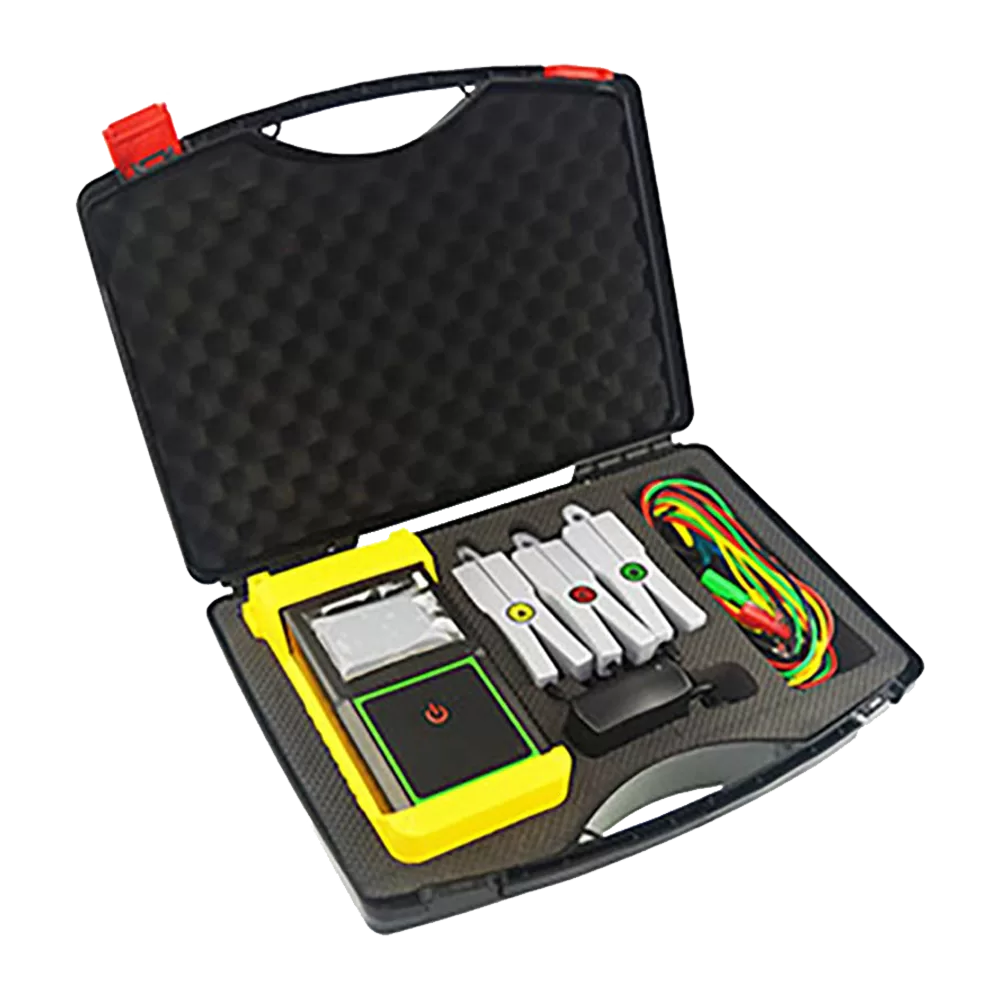
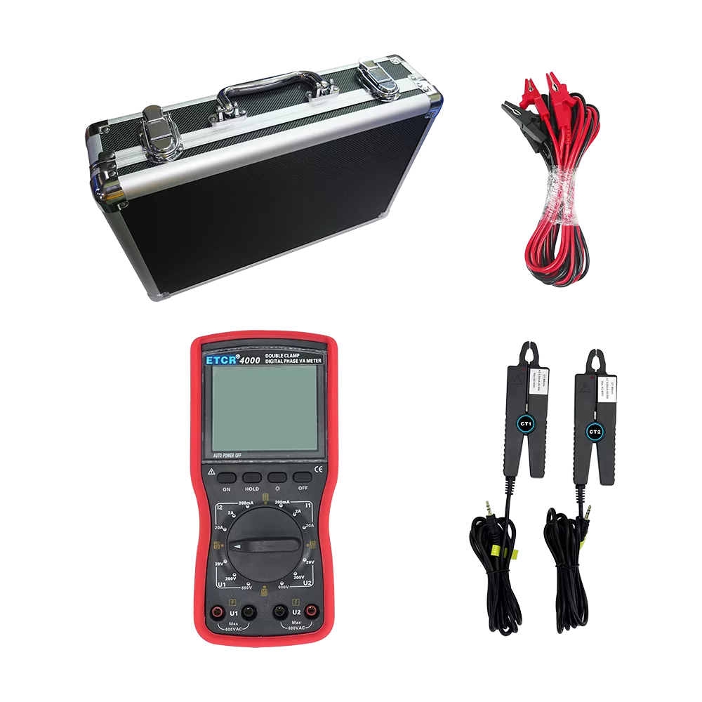
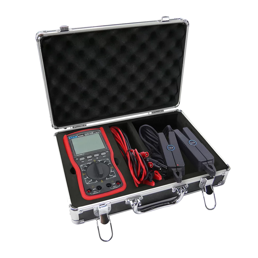
8.Complete standard accessories, ready to use
Equipped with 2 current clamps, test leads, batteries, data cable, instrument case and other full set of accessories.
9.Easy maintenance
Simple clamp jaw cleaning, easy battery replacement, and high durability.
Parameter
- 3.1. Base Conditions and Working Conditions
- General Specification
- 3.3. Intrinsic Error And Performance Index Under Base Conditions
| Influence Quantity | Base Condition | Working Conditions | Remark |
| Environment Temperature | 23℃±1℃ | -10℃~40℃ | |
| Environment Humidity | 40%~60% | <80% | |
| Signal Waveform | sine wave | sine wave | β=0.01 |
| Signal Frequency | 50HZ±1HZ | 45HZ~65HZ | |
| Meter Working Voltage | 9V±0.1V | 9V±1V | |
| The voltage amplitude when measure the phase frequency and phase sequence | 100V±20V | 30V~500V | |
| The current amplitude when measure the phase frequency and phase sequence | 1A±0.2A | 10mA~20.00A | —- |
| External Electric Magnetic Field | To be avoided | ||
| The Tested Wire Position | Measured wire at approximately the geometric center of the clamp | ||
| Function | Direct testing of the phase, AC current, AC voltage, AC leakage current, phase sequence; differentiate transformer group, inductive, capacitive circuit n; indirect testing of power factor, power. | |
| Power Supply | DC9V Alkaline dry batteries LR6 1.5V X6PCS | |
| Working Current | Open backlight max 35mA,the battery continues working about 15 hours; | |
| Close backlight, the meter power consumption about 5mA, the battery continues working 100 hours | ||
| Display Mode | LCD display, white screen backlight function, suitable for dark places | |
| LCD Size | LCD Size:70mmX62mm; Display Area:64mmX54mm | |
| Meter Dimensions | 196mmX92mmX54mm | |
| Jaw size | Φ8mm, 2 PCS | |
| Sampling Rate | About 3 times/second | |
| Range | AC Voltage: 0.00V~20V/200V/500V | |
| AC Current: 0.0mA~200mA/2A/20A | ||
| Phase: 0~360° | ||
| The amplitude range of the tested signal in measuring phase | Measure phase U1-U2: 30V~600V; | |
| Measure phase I1-I2: 10mA~20.00A | ||
| Measure phase U1-I2 or I1-U2: 10V~500V, 10mA~20.00A | ||
| Data Hold | In measurement, press HOLD key to hold data, “DH” symbol display | |
| Auto Shut Down | 15 minutes after boot up, the meter shuts down automatically without any operation, to reduce battery consumption | |
| Voltage Detection | When the battery voltage is lower than 7.8-8V, low battery symbol display, and remind to replace the battery. | |
| Meter Weight | Host: 574g(with battery) ; Current Clamp: 180gX2; Test wires : 180g; Instrument box: 957g; Total weight: 2.24kg (include accessories) | |
| Working Temperature | -10℃~40℃; below 80%RH | |
| Store Temperature | -10℃~60℃; below 70%RH | |
| Input Impedance | Test voltage each gears input impedance: 2MΩ; | |
| Measure phase U1U2 voltage input impedance :40kΩ | ||
| Withstand voltage | It took 1 minute to withstand 1000V/50Hz sine wave AC voltage between the meter line and the out shell. | |
| Insulation | ≥10MΩ between the instrument line and the casing, between the two voltage input terminals | |
| Structure | Double insulation | |
| Category | Measurement Range | Resolution | Intrinsic Error |
| Voltage | 20V | 0.01V | ±(0.5%range) |
| 200V | 0.1V | ||
| 500V | 1V | ||
| Current | 200mA | 0.1mA | ±(0.5%range) |
| 2A | 1mA | ||
| 10A | 10mA | ||
| Phase | 0~360° | 1° | ±1° |