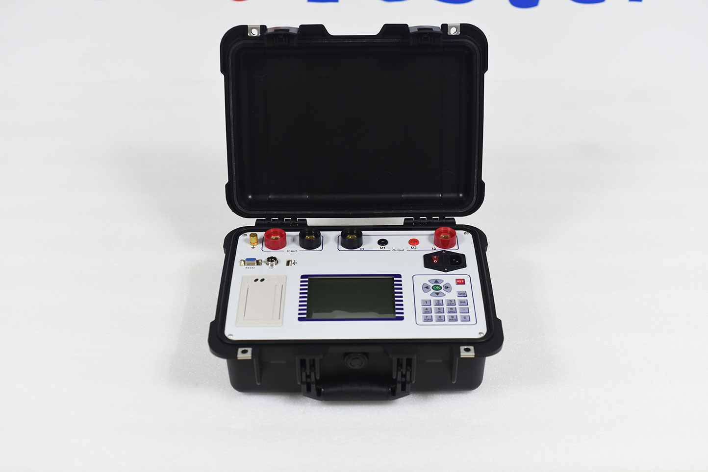
ZC-401A generator rotor AC impedance tester is the latest enhanced generator rotor AC impedance tester launched by our company. The instrument adopts the most advanced high-speed microprocessor technology, with more powerful functions, superior performance and more convenient use. The utility model has the characteristics of high reliability, simple operation, high test precision, small and light weight, etc. At present, it is at the leading level in China.
1. turn on the working power of the instrument, turn on the power switch, enter the interface diagram as shown in Figure 1 after the instrument is reset, press "↑" and "↓" to select "automatic test", and then press "OK" to enter the "automatic test parameter setting" interface as shown in the figure. The right side of the interface is the wiring diagram of the test.
Equipment number is used to distinguish different equipment, different test properties and times. To facilitate the search and technical management in historical data.
Voltage step - refers to the size and range of voltage figures (5-50v) between each data acquisition when the parameter data acquisition is based on the voltage.
Maximum voltage refers to the maximum voltage value to be tested in the test. The range is (0--600v). 1.1 times of its set value is the default overvoltage protection action value of the instrument.
Maximum current refers to the maximum current value to be tested in the test, with a range (0--120a). 1.1 times of its set value is the default overcurrent protection action value of the instrument.
2. connect the voltage regulator, instrument and the measured rotor winding according to the wiring diagram in the interface. A more detailed wiring diagram follows.
3. set the above parameters according to the test needs, move the cursor and select "start test" to enter the "automatic test" interface as shown in the figure.
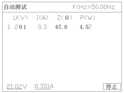
The top part of this interface displays the current voltage frequency, the middle part is the main display area, displaying the captured data records, and the bottom part is the real-time value of the current voltage and current. In this interface, adjust the voltage regulator and the boosting instrument to automatically collect and display the measured values of all parameters at each test point. Until the maximum set voltage value is reached, the buzzer of the instrument will sound a prompt tone to prompt that the data measurement is completed. At this time, the voltage regulator should be quickly returned to zero.
4. after the test, the instrument interface will switch to the "automatic test result" interface as shown in Figure 5.
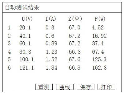
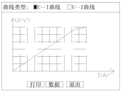
In the current interface, press "↑" and "↓" on the keyboard to traverse the measurement results, press "save" to save the current test results to the memory of the instrument for future reference, press "print" to print out the current test results through the panel printer, and press "curve" to draw the "voltage current relationship" curve as shown in Figure 6 according to the measured data.